Resonator device for damping the pressure oscillation within a combustion chamber and a method for operating a combustion arrangement

a technology of pressure oscillation and resonance device, which is applied in the direction of mechanical equipment, machines/engines, lighting and heating apparatus, etc., can solve the problems of adverse effects on the operation of the combustion chamber, particularly the efficiency of the gas turbine, and the inability of the combustion chamber to work satisfactorily under changing running conditions, etc., to achieve the effect of rapid load change of the combustion chamber

Inactive Publication Date: 2016-03-08
SIEMENS AG
View PDF11 Cites 2 Cited by
  • Summary
  • Abstract
  • Description
  • Claims
  • Application Information

AI Technical Summary

Benefits of technology

[0014]In particular, the flame generated by the heating element may be adapted, e.g. by utilizing a streaming material, to cause a convection of the gas filled within the container such that a temperature variation across different locations within the container rapidly balances to provide a homogeneous, or at least approximately homogeneous temperature distribution within the container. By providing the heating element adapted to generate a flame the temperature of the gas filled within the container may rapidly be changed thereby rapidly changing the resonance frequency of the resonator device. Thus, the resonator device is suitable for damping pressure oscillations within a combustion chamber under different running conditions. Thereby, the efficiency of the combustion chamber equipped with the resonator device may be improved. Further, it is not necessary to provide different resonator devices for different running conditions of the combustion chamber.
[0015]According to an embodiment the heating element is adapted to generate the flame using plasma assisted combustion. For an overview about plasma assisted combustion technology please see the paper “Plasma Assisted Combustion Technologies” by Matveev, S. Matveeva, E. Kirchuk, Proceedings of the European Combustion Meeting 2009 and the website http: / / www.plasmacombustion.com / iwepac.html. In a plasma assisted combustion a plasma is formed for example by application of a high electric field established between two electrodes which support burning of a fuel. Furthermore, the burning process may be confined or localized within a small volume by arranging for a gas flow, in particular a spiral-like gas flow, surrounding the core of the combustion process. The combustion process may also be confined or localized within a narrow flame provided at an outlet or at a nozzle of a plasma assisted combustion device. Plasma assisted combustion technologies are further characterized by a high heating power, high temperature of the flame and high velocity of the burning materials expelled from the plasma assisted combustion device. Due to the high heating power, high temperature of the flame and accurate controllability of the parameters of the flame the resonance frequency of the resonator device can rapidly be changed for damping pressure oscillations within a combustion chamber at different running conditions.
[0028]According to an embodiment the control system is adapted to control the heating element to change the temperature of the gas within the container, when the combustion chamber is operated in a condition different from the normal load condition such that a frequency of the pressure oscillation within the combustion space is equal (in particular at least approximately equal, in particular at least within an accuracy of 10%, in particular within an accuracy of 5% equal) to a resonance frequency of the container filled with the gas changed upon changing the temperature of the gas within the container. Thereby, the pressure oscillations within the combustion chamber may effectively be damped by the resonator device even for different load conditions of the combustion chamber. Thereby, the combustion chamber may be operated under different running conditions in an optimized way.
[0031]According to an embodiment the method of operating a combustion arrangement further comprises controlling the heating element to change the temperature of the gas within the container, when the combustion chamber is operated in a condition different from the normal load condition such that a frequency (changed compared to the frequency under normal load condition) of the pressure oscillation within the combustion space is equal (in particular at least approximately equal, in particular at least within an accuracy of 10%, in particular 5% equal) to a resonance frequency of the container changed upon changing the temperature of the gas within the container. Thereby, the pressure oscillation within the combustion chamber may effectively be damped by the resonator device even under changing load conditions of the combustion chamber.
[0032]According to an embodiment the method of operating a combustion arrangement further comprises increasing the temperature of the gas within the container at a rate of at least 50° C. per second. By changing the temperature of the gas within the container at this high rate a resonance frequency of the resonator device can rapidly be changed allowing consequently rapid load changes of the combustion chamber upon continuous damping of pressure oscillations within the combustion chamber.

Problems solved by technology

These pressure oscillations adversely affect the operation of the combustion chamber, in particular the efficiency of the gas turbine comprising the combustion chamber.
It has been observed that a combustion chamber may not work satisfactorily under changing running conditions.

Method used


Image

  • Resonator device for damping the pressure oscillation within a combustion chamber and a method for operating a combustion arrangement
  • Resonator device for damping the pressure oscillation within a combustion chamber and a method for operating a combustion arrangement
  • Resonator device for damping the pressure oscillation within a combustion chamber and a method for operating a combustion arrangement

Examples


Embodiment Construction

[0039]The illustration in the drawing is schematically. It is noted that in different figures, similar or identical elements are provided with the same reference signs or with reference signs, which are different from the corresponding reference signs only within the first digit.

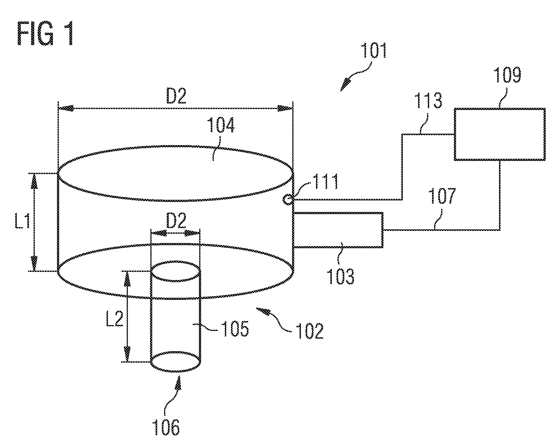
[0040]FIG. 1 schematically shows a resonator device 101 for damping a pressure oscillation within a combustion chamber. The resonator device 101 comprises a container 102 which is filled with a gas, such as air, and comprises a heating element 103 which is adapted as a reverse vortex plasma generator. The container 102 of the resonator device comprises a body portion 104 and a neck portion 105. The body portion 104 comprises a cylindrical container which is in communication with the neck portion 105 which also has a cylindrical shape but having a much smaller diameter D2 compared to the diameter D1 of the body portion 4 of the resonator device 101. The body portion has a length L1 and the neck portion has a ...


PUM


Abstract

A resonator device is provided for damping a pressure oscillation within a combustion chamber. The resonator device may comprise: a container filled with a gas; an opening in the container; and a heating element adapted to generate a flame. The flame is arranged to heat the gas within the container. The resonator device is comprised in a combustion arrangement comprising a combustion chamber for defining a combustion space for burning fuel. The container is connected to the combustion chamber such that an inside of the container is in communication with the combustion space via the opening. The resonator device has a resonance frequency equal to a pressure oscillation frequency within the combustion chamber under normal load conditions.

Description

CROSS REFERENCE TO RELATED APPLICATIONS[0001]This application is the US National Stage of International Application No. PCT / EP2011 / 053426 filed Mar. 8, 2011 and claims the benefit thereof. The International Application claims the benefits of European application No. 10159747.4 filed Apr. 13, 2010, both of the applications are incorporated by reference herein in their entirety.FIELD OF THE INVENTION[0002]The present invention relates to a resonator device for damping the pressure oscillation within a combustion chamber and to a method for operating a combustion arrangement. In particular, the present invention relates to a resonator device for damping a pressure oscillation within a combustion chamber which can be adjusted to damp an oscillation having a frequency which is changed upon changing the running condition of the combustion chamber. Further, the present invention relates to a method of operating a combustion arrangement involving damping of a pressure oscillation within the...

Claims


Application Information

Patent Timeline
Patent Type & Authority Patents(United States)
IPC IPC(8): F02C7/24F23M20/00F23R3/00
CPCF23R3/002F02C7/24F05D2260/963F23M20/005F23R2900/00013F23R2900/00014
Inventor BULAT, GHENADIE
Owner SIEMENS AG
Why Eureka
Try Eureka