
Methods and structures of integrated MEMS-CMOS devices

a technology of integrated mems and devices, applied in the field of mems (microelectromechanicalsystems), can solve the problems of increasing the cost of mems development, focusing on mems development, and reducing the focus of mems development, so as to reduce the risk of plasma damage, reduce the stiction of mems components, and reduce the differential bias

Active Publication Date: 2016-03-01
MCUBE INC
View PDF29 Cites 6 Cited by
  • Summary
  • Abstract
  • Description
  • Claims
  • Application Information

AI Technical Summary

Benefits of technology

The present invention is about a method and structure for creating an integrated MEMS-CMOS device. The structure includes a 3-axis inertial sensing device with single or dual proof mass configurations. The device also includes dummy regions and symmetric electrodes to reduce bias, metal structures for plasma damage protection, stop structures for reduced stiction, jointed spring structures for reduced spring rotation, and U-shaped members for spring assembly. The method of fabrication reduces risk of deformation and device failure during processes such as MEMS etching and cap bonding. Additionally, the invention presents methods and structures to protect CMOS circuits from plasma-induced damage by grounding and providing an alternate path for the CMOS circuits until the MEMS layer is completely etched.

Problems solved by technology

Although highly successful, ICs and in particular MEMS still have limitations.
Similar to IC development, MEMS development, which focuses on increasing performance, reducing size, and decreasing cost, continues to be challenging.
Additionally, applications of MEMS often require increasingly complex microsystems that desire greater computational power.
Unfortunately, such applications generally do not exist.

Method used


Image

  • Methods and structures of integrated MEMS-CMOS devices
  • Methods and structures of integrated MEMS-CMOS devices
  • Methods and structures of integrated MEMS-CMOS devices

Examples


Embodiment Construction

[0075]The present invention is directed to MEMS (Micro-Electro-Mechanical-Systems). More specifically, embodiments of the invention provide methods and structure for improving integrated MEMS devices, including inertial sensors and the like. Merely by way of example, the MEMS device can include at least an accelerometer, a gyroscope, a magnetic sensor, a pressure sensor, a microphone, a humidity sensor, a temperature sensor, a chemical sensor, a biosensor, an inertial sensor, and others. But it will be recognized that the invention has a much broader range of applicability.

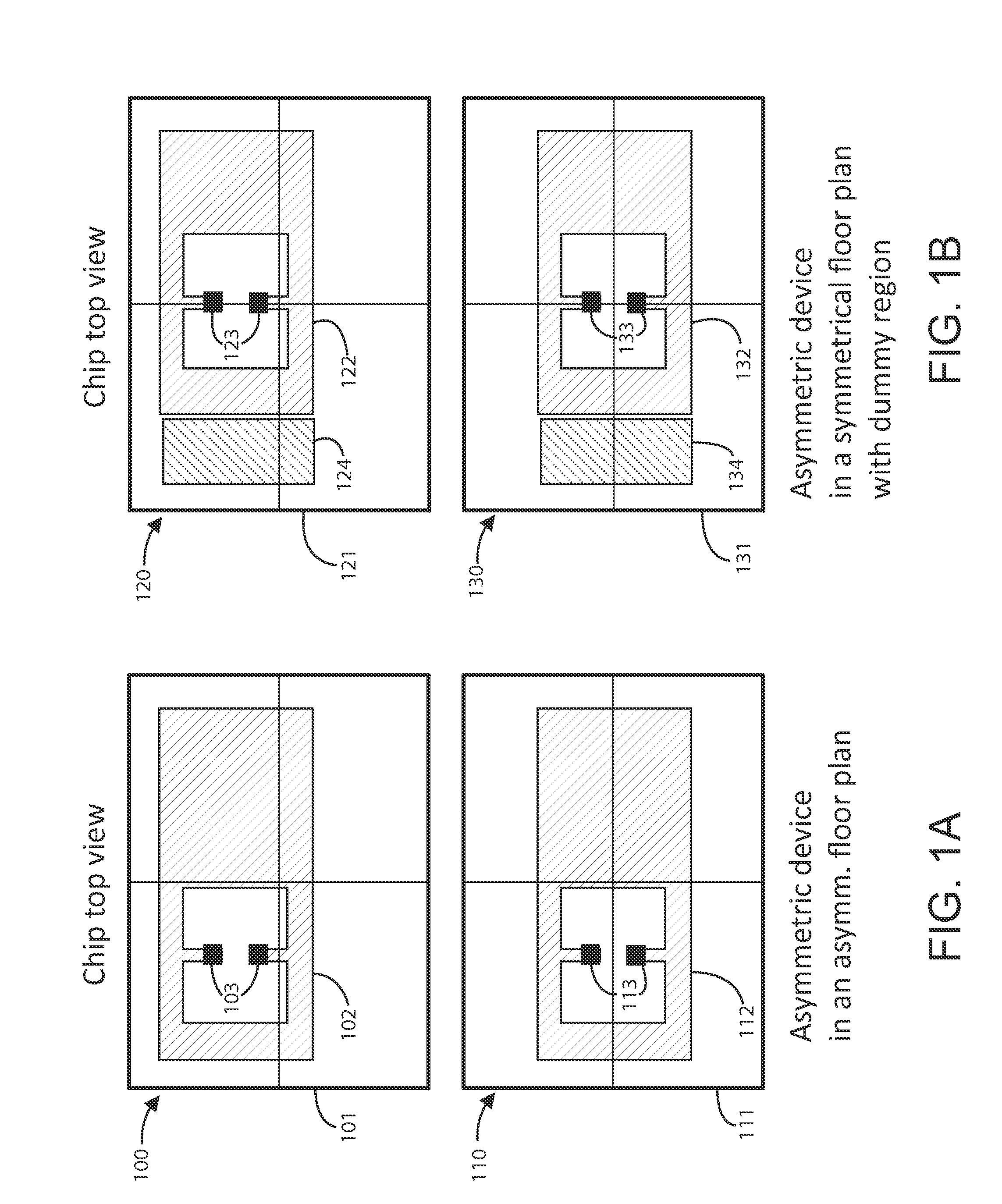
[0076]FIG. 1A is a simplified diagram illustrating a top view of an integrated circuit chip that includes an asymmetric device in an asymmetric floor place. Here, two configurations 100, 110 are shown with an asymmetrical device 102, 112 having two anchor points 103, 113 overlying a substrate member 101, 111. The top configuration 100 has the anchors 103 configured on the upper left portion of the substrate 101, a...


PUM

PropertyMeasurementUnit
resistanceaaaaaaaaaa
plasma induced chargeaaaaaaaaaa
dynamic stabilityaaaaaaaaaa

Abstract

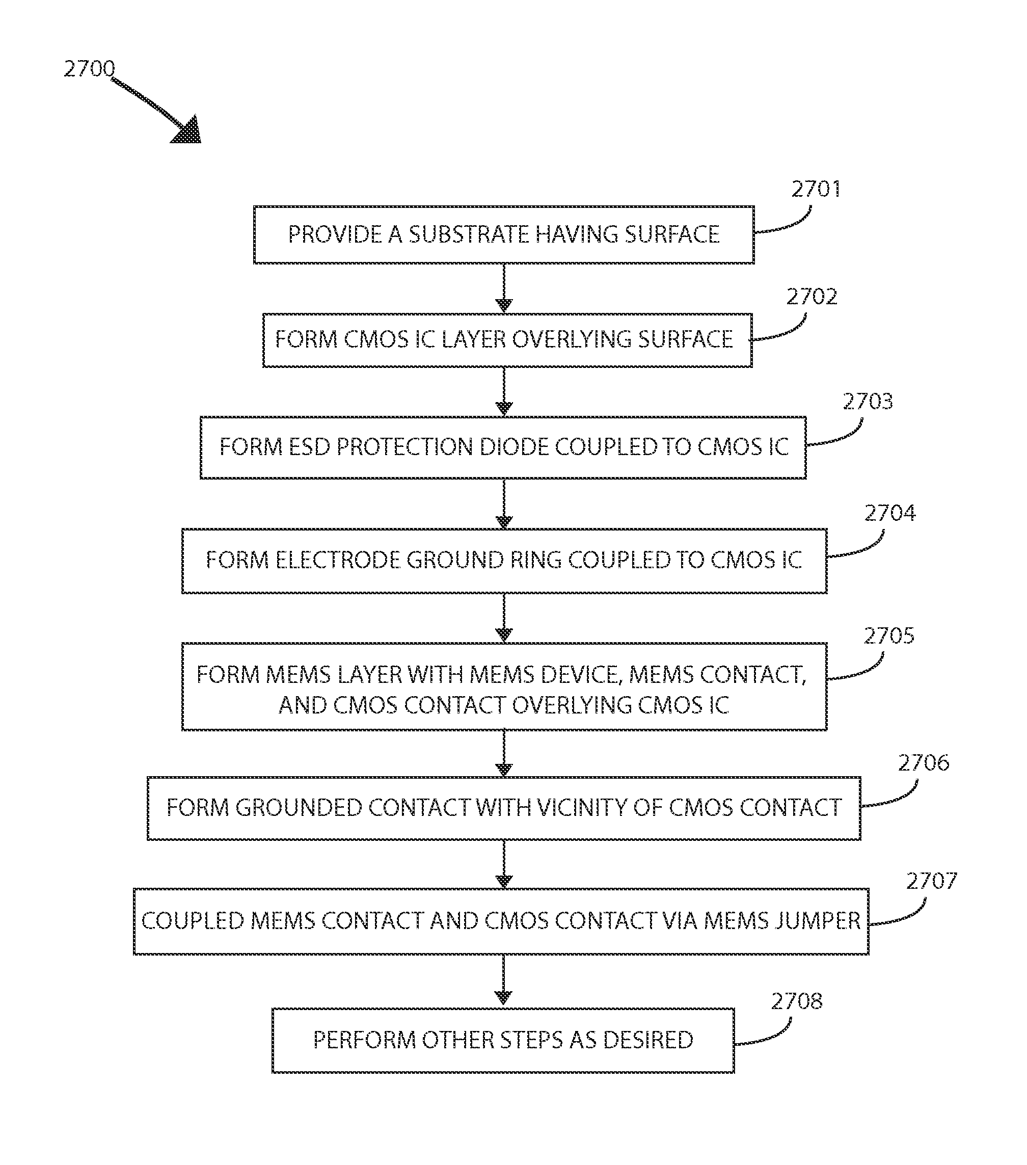
A method for fabricating an integrated MEMS-CMOS device uses a micro-fabrication process that realizes moving mechanical structures (MEMS) on top of a conventional CMOS structure by bonding a mechanical structural wafer on top of the CMOS and etching the mechanical layer using plasma etching processes, such as Deep Reactive Ion Etching (DRIE). During etching of the mechanical layer, CMOS devices that are directly connected to the mechanical layer are exposed to plasma. This sometimes causes permanent damage to CMOS circuits and is termed Plasma Induced Damage (PID). Embodiments of the present invention presents methods and structures to prevent or reduce this PID and protect the underlying CMOS circuits by grounding and providing an alternate path for the CMOS circuits until the MEMS layer is completely etched.

Description

CROSS-REFERENCES TO RELATED APPLICATIONS[0001]The present application claims priority to and incorporates by reference, for all purposes, the following patent applications: U.S. Prov. App. No. 61 / 609,248, filed Mar. 9, 2012, U.S. Prov. App. No. 61 / 745,496, filed Dec. 21, 2012.BACKGROUND OF THE INVENTION[0002]The present invention is directed to MEMS (Micro-Electro-Mechanical-Systems). More specifically, embodiments of the invention provide methods and structure for improving integrated MEMS devices, including inertial sensors and the like. Merely by way of example, the MEMS device can include at least an accelerometer, a gyroscope, a magnetic sensor, a pressure sensor, a microphone, a humidity sensor, a temperature sensor, a chemical sensor, a biosensor, an inertial sensor, and others. But it will be recognized that the invention has a much broader range of applicability.[0003]Research and development in integrated microelectronics have continued to produce astounding progress in CM...

Claims


Application Information

Patent Timeline
Patent Type & Authority Patents(United States)
IPC IPC(8): H01L29/66B81B3/00B81C1/00H01L27/06
CPCH01L29/66007B81B3/0013B81B3/0086B81C1/00238B81C1/00801H01L27/0688B81B2203/0163B81C2201/0132B81B7/0022B81B7/0064B81B2207/094B81C2201/05B81C2203/0735
Inventor SRIDHARAMURTHY, SUDHEER, S.LEE, TE-HSE, TERRENCERASTEGAR, ALI, J.STANCU, MUGURELYANG, XIAO, CHARLES
Owner MCUBE INC
Learn More