
Method for operating a gasifier

a gasifier and gas technology, applied in the direction of gasification process details, granular/pulverulent flue gasification, combustible gas production, etc., can solve the problems of reducing the useful life aqueous corrosion on the inside surface of the steel vessel, and the gasification process may produce highly corrosive byproducts

Active Publication Date: 2016-02-16
AIR PROD & CHEM INC
View PDF10 Cites 0 Cited by
  • Summary
  • Abstract
  • Description
  • Claims
  • Application Information

AI Technical Summary

Benefits of technology

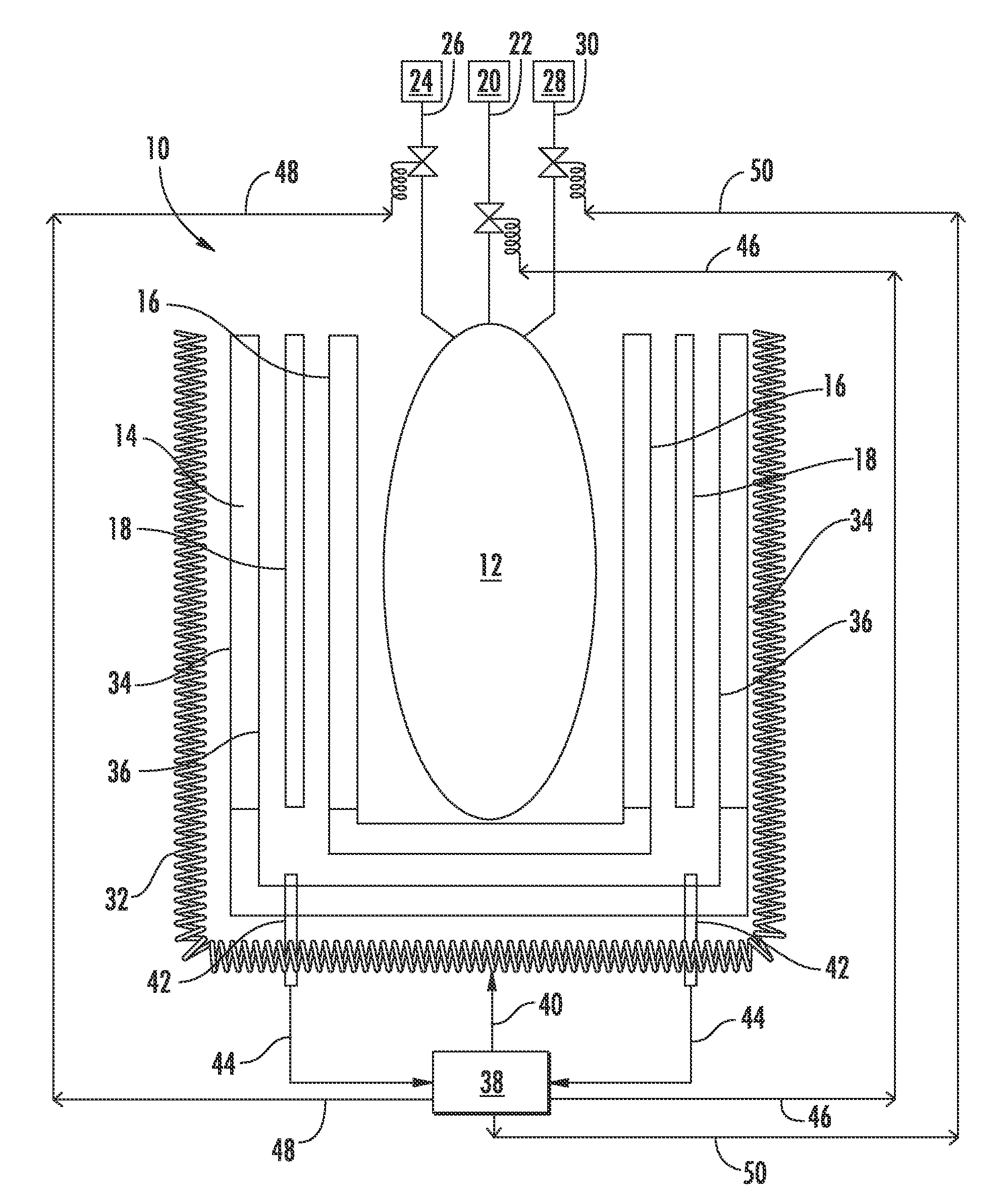
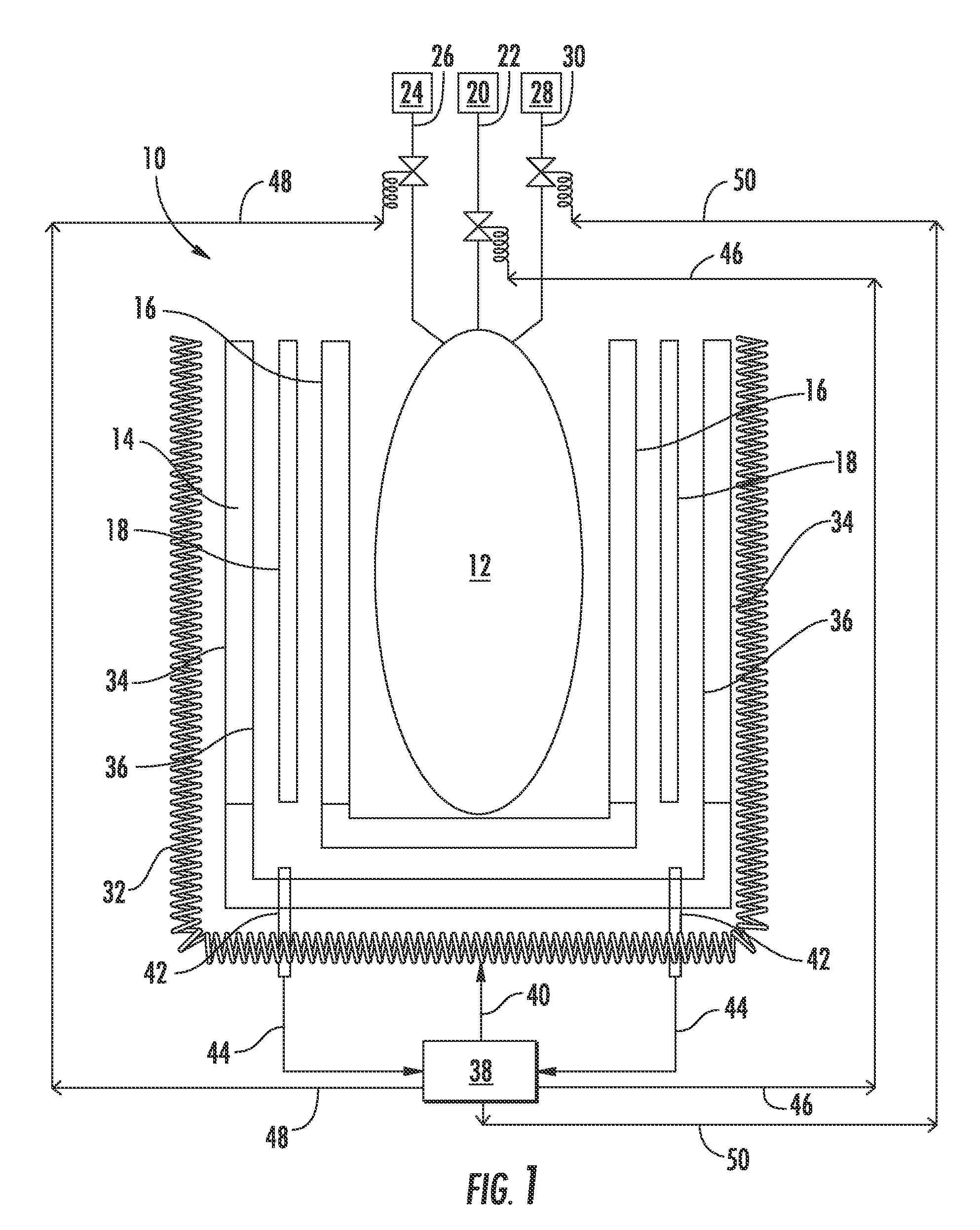
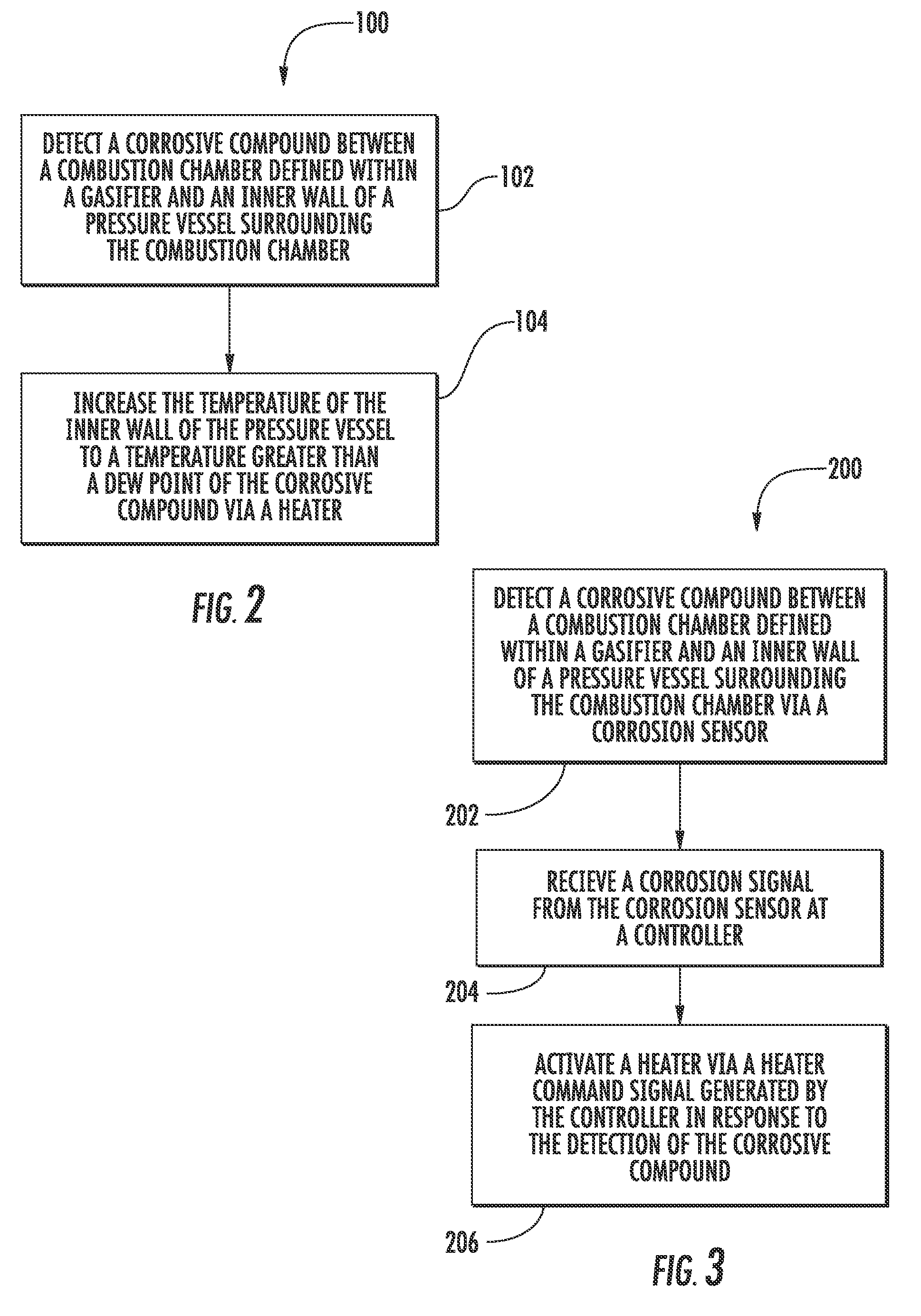
[0009]Another embodiment of the present invention is a method for operating a gasifier. The method includes detecting a corrosive compound between a combustion chamber defined within the gasifier and an inner wall of a pressure vessel surrounding the combustion chamber via a corrosion sensor where the corrosion sensor generate a corrosion signal that is indicative of the presence of the corrosive compound. The method also includes receiving the corrosion signal at a controller, and activating a heater that at least partially surrounds the pressure vessel via a heater command signal generated by the controller in response to the detection of the corrosive compound so as to increase the inner wall temperature of the pressure vessel to a temperature that is above a dew point of the corrosive compound.

Problems solved by technology

The gasification process may produce highly corrosive byproducts, such as ammonium chloride.
If the dew point of the inner surface of the steel vessel is less than the dew point of the corrosive byproducts, then the corrosive byproducts may condense on an inside surface of the steel vessel, causing aqueous corrosion on the inside surface of the steel vessel.
The aqueous corrosion on the inside surface of the steel vessel is undesirable in that it may result in unplanned outages for maintenance and / or repair and ultimately reduces the useful life of the steel vessel.
Other attempts have involved costly external wind deflectors and variations in the design of the brick insulation.

Method used


Image

  • Method for operating a gasifier
  • Method for operating a gasifier
  • Method for operating a gasifier

Examples


Embodiment Construction

[0017]Reference will now be made in detail to present embodiments of the invention, one or more examples of which are illustrated in the accompanying drawings. The detailed description uses numerical and letter designations to refer to features in the drawings. Like or similar designations in the drawings and description have been used to refer to like or similar parts of the invention.

[0018]Each example is provided by way of explanation of the invention, not limitation of the invention. In fact, it will be apparent to those skilled in the art that modifications and variations can be made in the present invention without departing from the scope or spirit thereof. For instance, features illustrated or described as part of one embodiment may be used on another embodiment to yield a still further embodiment. Thus, it is intended that the present invention covers such modifications and variations as come within the scope of the appended claims and their equivalents.

[0019]FIG. 1 is a si...


PUM

PropertyMeasurementUnit
temperatureaaaaaaaaaa
temperaturesaaaaaaaaaa

Abstract

A method for operating a gasifier includes detecting a corrosive compound between a combustion chamber defined within the gasifier and an inner wall of a pressure vessel that at least partially surrounds the combustion chamber via a corrosion sensor and increasing the temperature of the inner wall of the pressure vessel to a temperature that is greater than a dew point of the corrosive compound via a heater that at least partially surrounds the pressure vessel. The method may also include adjusting a flow of at least one of a fuel, an oxidant and a diluent to the gasifier in response to the detection of the corrosive compound so as to modify the dew point of the corrosive compound.

Description

CROSS REFERENCE TO RELATED APPLICATIONS[0001]The present application claims priority as a continuation in part of U.S. application Ser. No. 12 / 890,916 having a filing date of Sep. 27, 2010 and United U.S. application Ser. No. 12 / 890,935 having a filing date of Sep. 27, 2010, both of which are incorporated herein by reference in their entirety.FIELD OF THE INVENTION[0002]The present invention generally involves a method for operating a gasifier. Specific embodiments of the present invention may include a method for operating a gasifier that includes adjusting conditions within or surrounding the gasifier based on detection of corrosive compound formation or deposits within the gasifier during operation.BACKGROUND OF THE INVENTION[0003]An Integrated Gasification Combined Cycle (IGCC) is known in the art for converting petroleum coke or coal into synthetic gas which may then be supplied to a gas turbine to generate power. The synthetic gas, a clean burning fuel, may be burned directly ...

Claims


Application Information

Patent Timeline
Patent Type & Authority Patents(United States)
IPC IPC(8): C10J3/74C10J3/48C10J3/72
CPCC10J3/723C10J3/485C10J3/74C10J2300/0959C10J2300/1269C10J2300/1276C10J2300/1653C10J2300/1846Y02E20/18
Inventor GOLLER, GEORGE, ALBERT
Owner AIR PROD & CHEM INC
Learn More