Advancing/retracting actuation device with meshing chain

a technology of advancing/retracting actuation and meshing chain, which is applied in the direction of lifting devices, chain elements, gearing, etc., can solve the problems of excessive work burden on the apparatus, complicated apparatus configuration, and difficulty in adjusting the rotation phase, so as to avoid vibration, noise, and speed fluctuation of the interlocking chain. the effect of smooth driving

Active Publication Date: 2016-02-09
TSUBAKIMOTO CHAIN CO
View PDF44 Cites 0 Cited by
  • Summary
  • Abstract
  • Description
  • Claims
  • Application Information

AI Technical Summary

Benefits of technology

The present invention provides an interlocking chain type forward and backward actuating device that avoids an increase in work burden on apparatus assembly, adjustment of rotation phases, and maintenance, smoothly advances and retreats a driven body near an installation surface, and avoids pulsation, vibration, noise, and speed fluctuation of the interlocking chains. The device includes a chain guide groove that ensures smooth movement for meshing between hook-shaped inner and outer tooth plates. The chain positioning guide portion supports not only chain disengaged portions but also the rigid chain part in which the interlocking chains are interlocked and made rigid, thus more reliably avoiding pulsation, vibration, noise, and speed fluctuation of the interlocking chains. The length of the straight extending portion is equal to or longer than the pin-to-pin distance between the pair of front and rear connecting pins, making the interlocking chains more smoothly driven and more reliably avoiding occurrence of pulsation, vibration, noise, and speed fluctuation of the interlocking chains.

Problems solved by technology

However, the conventional interlocking chain type lifting apparatus 800 has problems in apparatus assembly and maintenance as shown in FIG. 8.
Specifically, to engage a pair of lifting interlocking chains 810 with each other at a right timing by synchronizing rotation phases of a pair of lifting sprockets 820 with each other, an operation for adjusting the rotation phases involves an excessively heavy work burden.
Further, the apparatus configuration becomes complicated, and this involves an excessively heavy work burden on apparatus assembly and maintenance.

Method used


Image

  • Advancing/retracting actuation device with meshing chain
  • Advancing/retracting actuation device with meshing chain
  • Advancing/retracting actuation device with meshing chain

Examples


example

[0033]Hereinafter, an interlocking chain type forward and backward actuating device of one embodiment of the present invention will be described based on the drawings.

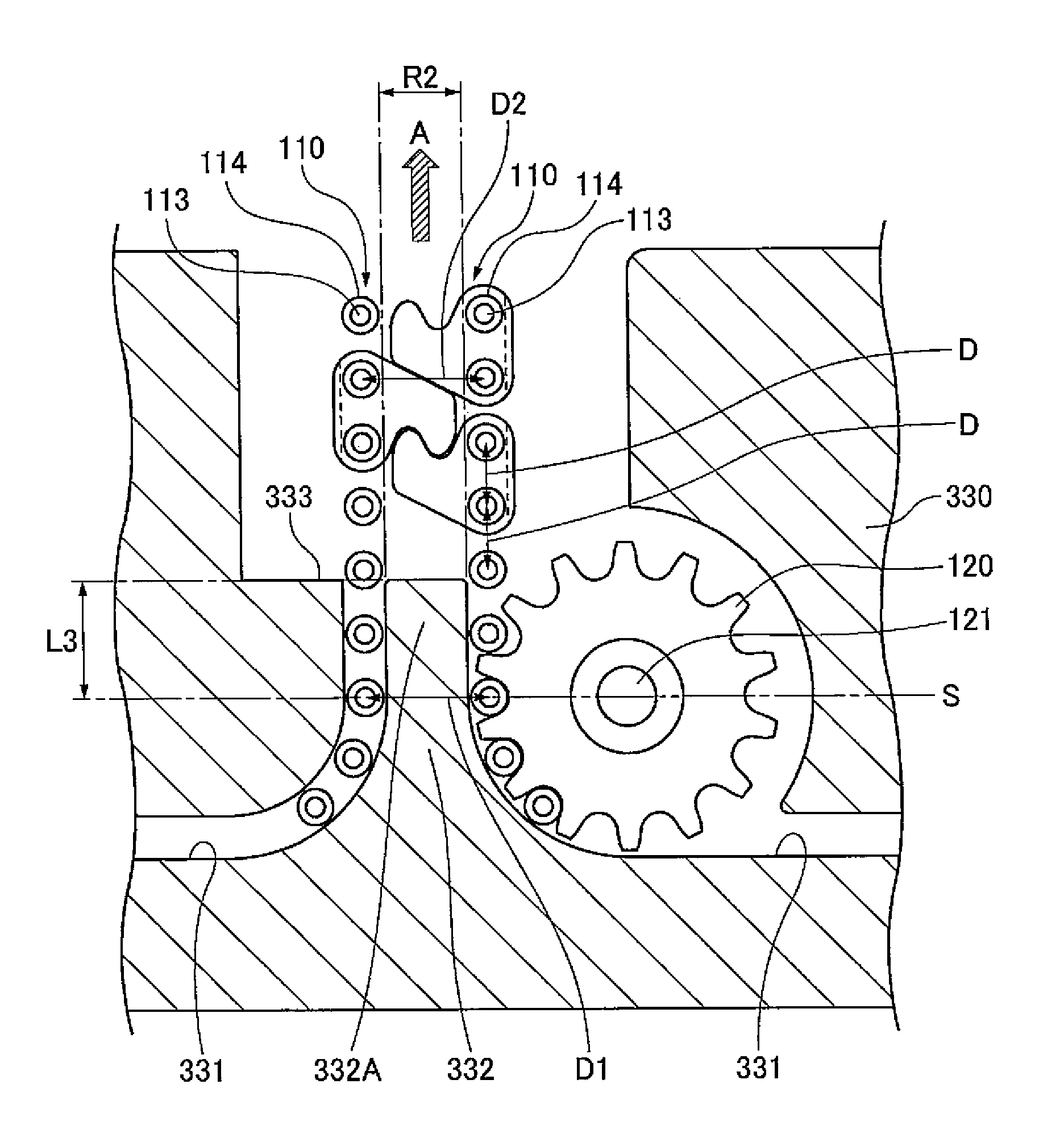
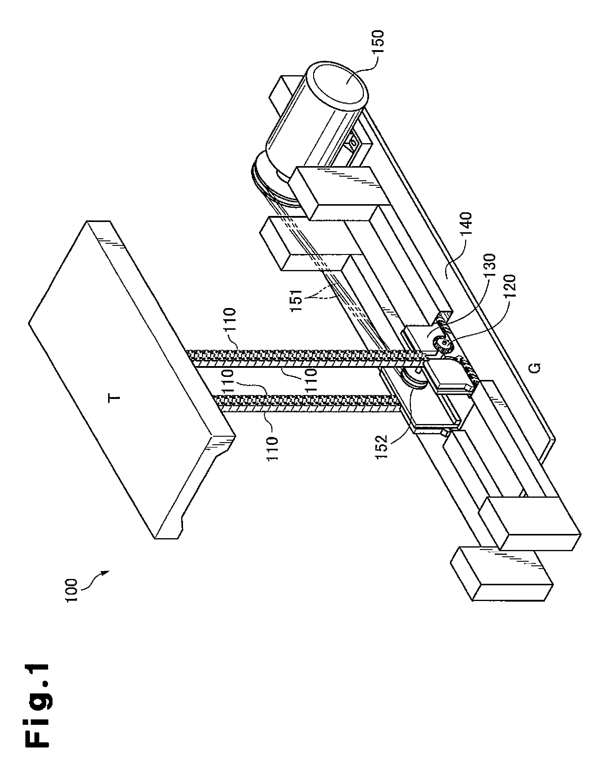
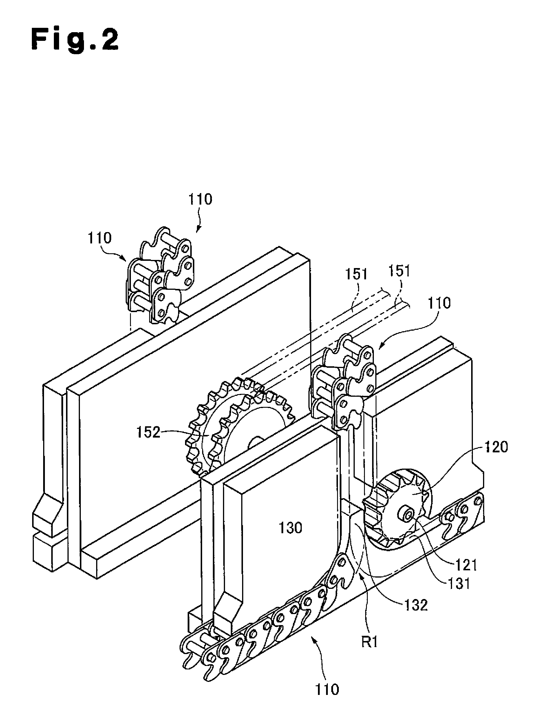
[0034]FIG. 1 is a general perspective view of an interlocking chain type forward and backward actuating device according to one embodiment of the present invention. FIG. 2 is a partially enlarged view of the vicinity of a drive sprocket and interlocking chains shown in FIG. 1. FIG. 3 is a perspective view showing an exploded state and a disengaged state of the interlocking chains. FIG. 4 is a partially enlarged view of the vicinity of the drive sprocket and the interlocking chains shown in FIG. 1. FIG. 5 is a partially enlarged view corresponding to FIG. 4, illustrating a first modification. FIG. 6 is a partially enlarged view corresponding to FIG. 4, illustrating a second modification. FIG. 7 is a partially enlarged view corresponding to FIG. 4, illustrating a third modification.

[0035]First, an interlocking chain type...


PUM


Abstract

An interlocking chain type forward and backward actuating device is provided that does not increase workload involved in assembling the device, adjusting the rotation phase, and servicing and maintaining the device. The device is capable of smoothly actuating a driven body by advancing and retracting the body, and of preventing any pulsation or the like of the meshing chain. The interlocking chain type forward and backward actuating device includes chain-guide grooves formed so as to equalize an interlocked-state pin-to-pin distance (D1) between a pair of connecting pins that face each other in a chain interlocking imaginary plane (S) and a rigid-state pin-to-pin distance (D2) between a pair of connecting pins.

Description

CROSS REFERENCE TO RELATED APPLICATIONS[0001]This application is a National Stage Application under 35 U.S.C. 371 and claims the benefit of PCT Application No. PCT / JP2011 / 080166 having an international filing date of 27 Dec. 2011, which designated the United States, and which PCT application claimed the benefit of Japanese Patent Application No. 2011-015066 filed on 27 Jan. 2011, the entire disclosures of which is incorporated by reference herein.FIELD OF THE INVENTION[0002]The present invention relates to a drive unit used in manufacturing facilities in various manufacturing fields, transportation facilities in the transportation field, nursing care facilities in medical and welfare fields, and stage facilities in art fields, and advancing and retreating a driven body such as a workpiece in parallel to an installation face, in particular, to an interlocking chain type forward and backward actuating device using interlocking chains as drive media for advancing / retreating movement.BA...

Claims


Application Information

Patent Timeline
Patent Type & Authority Patents(United States)
IPC IPC(8): F16G13/20F16H19/04B66F3/06
CPCF16H19/04B66F3/06F16G13/20Y10T74/18096
Inventor SAJI, TOMOYUKIMURAKAMI, KEISUKE
Owner TSUBAKIMOTO CHAIN CO
Why Eureka
Try Eureka