Road milling machine, in particular small milling machine, for working road surfaces

a road surface and small technology, applied in the field of road milling machines, can solve the problems of increased friction and wear, considerable damage to and loss of performance, so as to reduce the susceptibility to failure of the drum gearbox and broaden the range of possible applications of the road milling machine

Active Publication Date: 2016-02-02
WIRTGEN GMBH
View PDF12 Cites 0 Cited by
  • Summary
  • Abstract
  • Description
  • Claims
  • Application Information

AI Technical Summary

Benefits of technology

[0010]It is therefore the object of the present invention to improve a road milling machine, in particular a small milling machine, of the type first mentioned above to the effect that the susceptibility to failure of the drum gearbox is reduced and the range of possible applications of the road milling machine is broadened.
[0012]The invention provides for the reduction gearbox to be arranged entirely outside of the drum casing so that the second housing part protruding into the drum casing can be designed essentially rotationally symmetrically with a minimum cross-section. Blocking of the milling drum by milled material is thus safely precluded, in which case the wear on the interior skin of the milling drum and the second housing part is also additionally minimized.
[0013]A further advantage is offered in that a multitude of special milling drums with reduced cutting circle as well as milling drums with variable diameter in axial direction, such as spherically shaped milling drums, can be used. The vertical cut-out arranged at the underside between the reduction gearbox and the connecting flange can accommodate a movable side plate which can largely prevent milled material from escaping from the interior of the drum casing with different milling depths of the drum casing.
[0014]It is preferably intended for the reduction gearbox to be located entirely inside the first housing part and for the output shaft to extend from the reduction gearbox into the second housing part located inside the drum casing. It is thus intended for the housing part located inside the drum casing to accommodate only the output shaft. Owing to the fact that the second housing part accommodates only the output shaft as well as the bearing required for the same, the outer diameter of the second housing part is reduced to a diameter that is essentially determined only by the outer diameter of the bearing and the wall thickness of the gearbox housing. In view of this, the diameter of the second housing part can be reduced to the greatest possible extent and can assume an essentially rotationally symmetrical cross-sectional shape.
[0018]A particularly preferred embodiment intends for a feeding device in the first housing part to feed oil into the upper area of the reduction gearbox. From there the oil can flow, for example, via a channel, into the housing part protruding into the drum casing, in this fashion enabling the circulation of oil in a single oil supply system.

Problems solved by technology

Such gearbox housing protruding into the drum casing has the disadvantage that milled material penetrating into the interior of the milling drum collects in the narrow gap between the gearbox housing and the interior skin of the milling drum where it leads to increased friction and wear and, ultimately, to a loss in performance.
In extreme cases, the milled material can become wedged in the gap and block the milling drive which can cause considerable damage to the road milling machine.
This is aggravated further by the fact that not only the narrow gap alone but the wedged shape of the gap causes the problems when a milling drum of circular cross-section is put over an extension housing that is eccentric or non-rotationally symmetrical to the output shaft.
A further disadvantage of the known prior art is that milling drums with a relatively small diameter or a spherical shape cannot be used due to the fact that the gearbox housing makes almost full use of the free interior space of the milling drum towards the top.
Finally, a further disadvantage of the known design is to be seen in the fact that the housing part located outside of the drum casing is at a higher level than the housing part located inside the drum casing, thus necessitating two separate oil supply systems.
The separate oil supply systems require additional components, such as pumps or oil coolers, and exhibit temperature problems due to the lack of temperature compensation between the two gearbox parts.

Method used


Image

  • Road milling machine, in particular small milling machine, for working road surfaces
  • Road milling machine, in particular small milling machine, for working road surfaces
  • Road milling machine, in particular small milling machine, for working road surfaces

Examples


Embodiment Construction

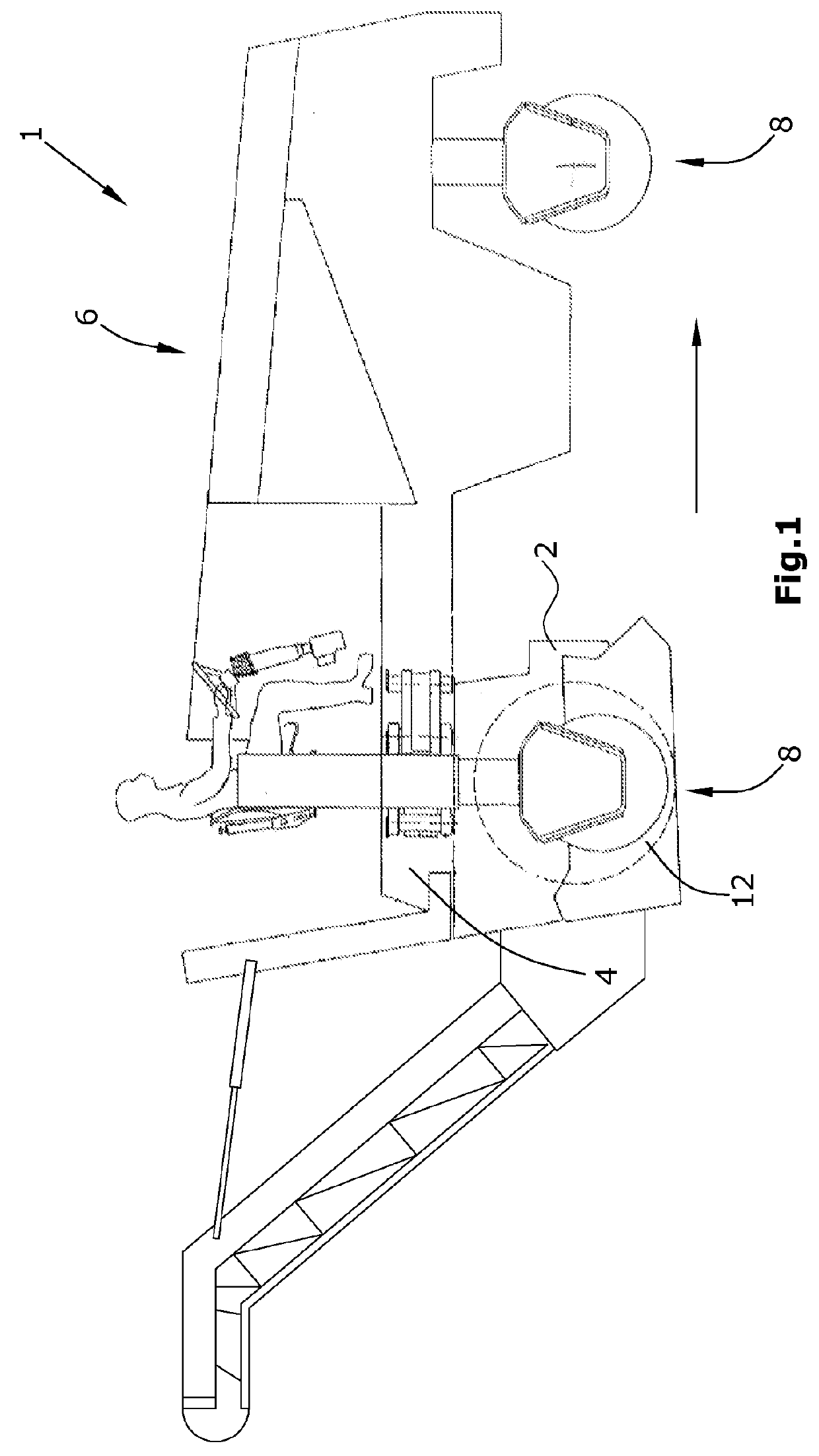
[0031]The automotive road milling machine 1 for working road surfaces depicted in FIG. 1, for example, a small milling machine, comprises a machine frame 4 as well as a drive engine 6 for the driving of travelling mechanisms 8 and of working devices. In the embodiment in FIG. 1, the travelling mechanisms 8 are comprised of wheels but may also be comprised, wholly or in part, of crawler tracks. The main working device is comprised of a milling drum 12 for milling the road surface, where said milling drum 12 is capable of being driven by a milling drum drive with a drum gearbox 10.

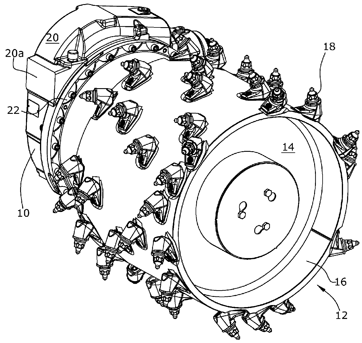
[0032]FIG. 2 shows a perspective view of the mounted milling drum 12 with a connecting flange 14 and a drum 16 which carries a multitude of systematically arranged tools 18.

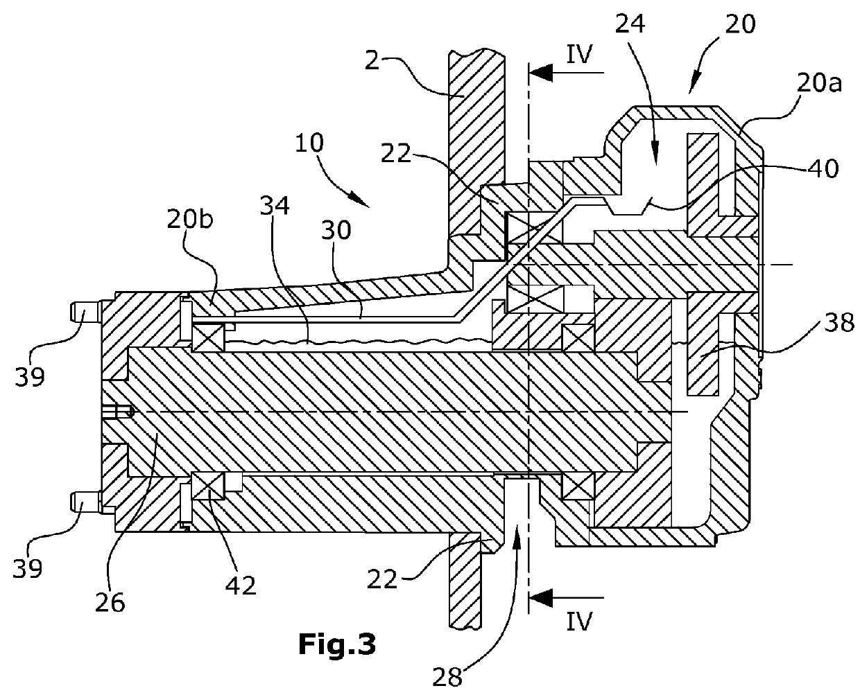
[0033]FIG. 3 shows a section through the drum gearbox 10 with a gearbox housing 20 which can be fastened at a front wall of the drum casing 2 in such a fashion that a first housing part 20a with a two-stage reduction gearbox 24 is arrange...


PUM


Abstract

In a road milling machine, in particular small milling machine, for working road surfaces, with a machine frame, with a milling drum supported at the machine frame in a drum casing, with a milling drum drive comprising a drum gearbox mounted at the drum casing, where the drum gearbox comprises a gearbox housing with a connecting flange for mounting at the drum casing, as well as a reduction gearbox and an output shaft for driving the milling drum, it is provided for the following features to be achieved: that the gearbox housing comprises, on the underside between the reduction gearbox and the connecting flange, a cut-out dividing the gearbox housing and extending radially inwards in such a fashion that the reduction gearbox is arranged in a first housing part arranged outside of the drum casing, and the output shaft is arranged in a second housing part protruding into the drum casing.

Description

BACKGROUND OF THE INVENTION[0001]1. Field of the Invention[0002]The invention relates to a road milling machine, in particular small milling machine, for working road surfaces.[0003]2. Description of the Prior Art[0004]Such small milling machine is known, for example, under the designation Wirtgen W 50 DC. The basic design of a generic road milling machine is known from DE 196 31 042 A1.[0005]The small milling machine comprises a cantilevered milling drum which is mounted at the machine frame in a drum casing and can be driven by a milling drum drive.[0006]The known milling drum drive comprises a drum gearbox that is arranged in part inside the drum casing and in part outside of the drum casing. To this effect, the drum gearbox is attached at a front wall of the drum casing by means of a connecting flange.[0007]In a known drum gearbox according to DE 10 2010 014 529 A, at least one part of the reduction gearbox is arranged in the gearbox housing located in the drum casing so that, i...

Claims


Application Information

Patent Timeline
Patent Type & Authority Patents(United States)
IPC IPC(8): E01C23/12E01C23/088
CPCE01C23/088E01C23/127
Inventor FRANZMANN, DIRKBERNING, CHRISTIANVERHAELEN, PHILIPBARIMANI, CYRUSHAHN, GUNTER
Owner WIRTGEN GMBH
Why Eureka
Try Eureka