Converter for an electrical circuit designed to supply electrical propulsion power on board a motor vehicle

a technology of electrical circuit and converter, which is applied in the direction of electric vehicle, battery/cell, electric device, etc., can solve the problems of zvs technique not allowing satisfactory efficiency at low load, the inversion current in each cell is kept relatively high, and the induction current is reduced.

Active Publication Date: 2016-02-02
VALEO SYST DE CONTROLE MOTEUR
View PDF8 Cites 0 Cited by
  • Summary
  • Abstract
  • Description
  • Claims
  • Application Information

AI Technical Summary

Benefits of technology

[0025]The invention results from the finding that it is possible to use a converter for a motor vehicle so as to obtain a current modulation per cell that is sufficiently high to use the ZVS method in a critical conduction mode while minimizing the modulation of the flux in the magnetic circuit so as to limit the power losses and to allow the use of high-saturation materials, notably Fe—Si-based materials.
[0029]By virtue of the invention, it is possible to use an electrical circuit as a multi-cell converter capable of using a ZVS method operating in critical mode because the coupling of the inductive elements makes it possible to greatly reduce the inversions of flux in the whole magnetic circuit—according to the differential mode—while the current inversions in each cell are kept relatively high—according to the common mode.
[0031]Further, materials which could not have been used in this type of converter with high frequencies and great current inversions can be introduced without generating unacceptable levels of “iron” losses, that is to say losses due to the flux inversions or modulations. Therefore, the invention makes it possible to reduce the volume of the magnetic materials used in converters since the latter accept much higher inductions.

Problems solved by technology

In the case of electrical vehicles and more particularly of hybrid vehicles, the volume and weight of these cells are also important criteria and, notably, the usually considerable size of the inductive elements—a coil 110 in this example—becomes problematic.
Although the use of this ZVS method with a fixed switching frequency may be satisfactory when the converter is operating at high load, it seems that this ZVS technique does not allow satisfactory efficiency at low load.
Specifically, it seems problematic that the current is greatly modulated irrespective of the load, whether it be at low load, that is to say when the average current is close to zero (FIG. 7) or in the case of a high load, that is to say when the average current is, for example, close to 50 A (FIG. 6).
Problematically, it seems that this critical conduction mode generates current inversions in the inductive elements which make it difficult to design the latter.
In truth, the amplitude of the current inversions may be greater than 100% of the value of the peak current over a high-frequency range (between 20 kHz and 80 kHz for example) which makes the power losses in the inductor unacceptable in terms of temperature rise and efficiency.
Unfortunately, ferrite is a material which saturates with a relatively weak magnetic field relative to other, iron-based, magnetic materials.
The consequence is the considerable magnetic volume required to manufacture the inductive element, which may be unacceptable in a hybrid-vehicle application, or the limited power storage in these materials because of their very great permeability.

Method used


Image

  • Converter for an electrical circuit designed to supply electrical propulsion power on board a motor vehicle
  • Converter for an electrical circuit designed to supply electrical propulsion power on board a motor vehicle
  • Converter for an electrical circuit designed to supply electrical propulsion power on board a motor vehicle

Examples


Embodiment Construction

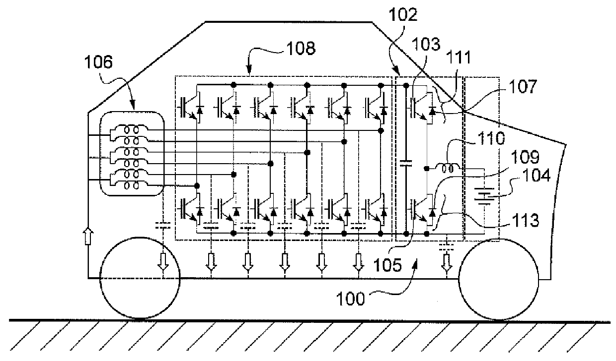
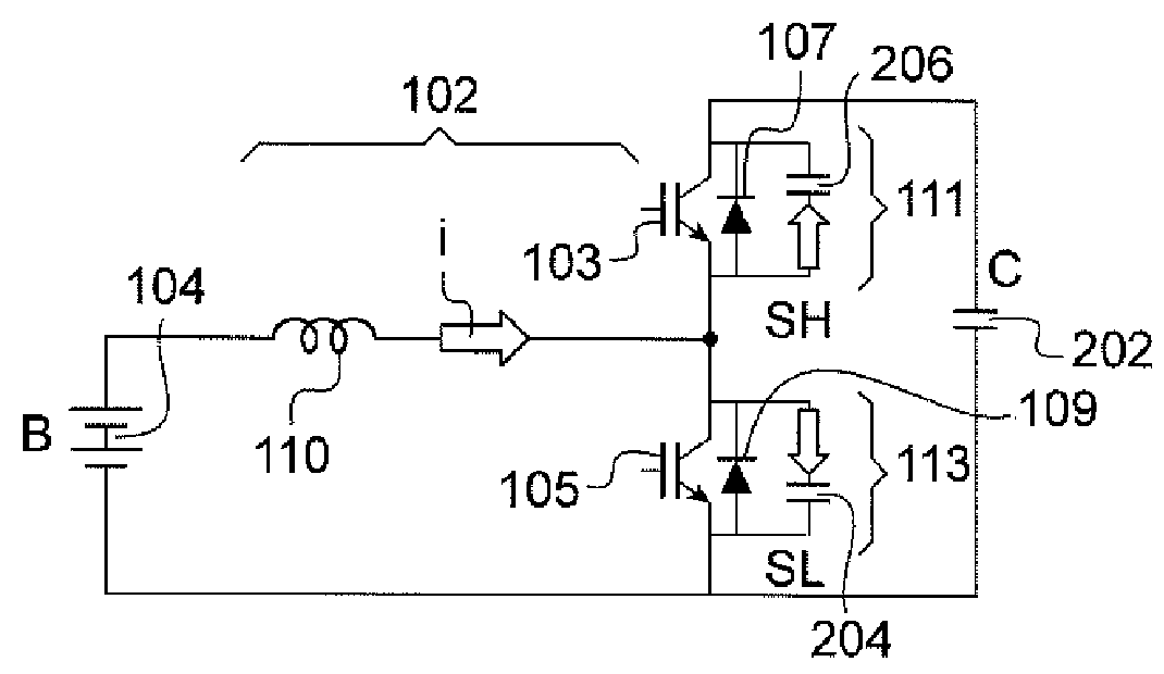
[0056]The identical elements, by structure or by function, appearing in different figures retain the same references unless specified otherwise.

[0057]FIG. 9 shows a magnetic circuit 900 according to the invention, that is to say comprising two cells 901 or 903 furnished with respective inductive elements 902 and 904—represented by coils—coupled so as to be able to be alternately controlled according to a common mode in which an apparent inductance of the said magnetic circuit 900 is relatively high, for example of the order of magnitude of the sum of the inductances LA and LB specific to each of the said inductive elements 902 and 904.

[0058]By virtue of such a high apparent inductance, the inversions of the magnetic flux in the circuit are limited—as described in detail below—which reduces the iron losses. According to a differential mode in which the apparent inductance of the said magnetic circuit is relatively low, for example of the order of magnitude of the leakage inductance o...


PUM

PropertyMeasurementUnit
specific inductancesaaaaaaaaaa
leakage inductanceaaaaaaaaaa
powersaaaaaaaaaa

Abstract

An electrical circuit for supplying electrical propulsion power on board a motor vehicle is disclosed. The electrical power is obtained from power delivered to the electrical circuit by a battery of the vehicle and converted by at least two cells. The circuit includes inductive elements connected to transistors for managing the current flowing in the inductive elements, and the inductive elements are coupled to form a magnetic circuit. The magnetic circuit is alternatively controlled according to a common mode in which an apparent inductance of the said magnetic circuit is of the order of magnitude of the sum of the inductances specific to each inductive element, or according to a differential mode in which the apparent inductance of the said magnetic circuit is of the order of magnitude of the leakage inductance of the coupling between the said coupled inductive elements.

Description

TECHNICAL FIELD OF THE INVENTION[0001]The present invention relates to a converter for an electrical circuit designed to provide electrical propulsion power on board a motor vehicle.BACKGROUND[0002]With reference to FIG. 1, it is known practice to furnish a vehicle 100, that is totally or partially electrically propelled, with a power converter 102 capable of raising the voltage of a battery 104 in order to power an electrical machine 106, typically via inverters 108.[0003]Because of the powers at work in such a converter 102, usually between 20 and 1000 kW, it may be worthwhile to make a multi-cell converter in which a power-supply current originating from the battery 104 is distributed amongst multiple conversion cells.[0004]The use of such a multi-cell converter faces a problem of cost notably because of the quantity of silicon required by switches 111 and 113 used in a cell, and notably in their transistors 103 or 105 and their power diodes 107 or 109.[0005]In the case of electr...

Claims


Application Information

Patent Timeline
Patent Type & Authority Patents(United States)
IPC IPC(8): B60L1/00B60L11/18B60L15/00
CPCB60L11/1805B60L15/007B60L2210/14Y02T10/7005Y02T10/7225Y10T29/49117B60L50/52Y02T10/64Y02T10/70Y02T10/72
Inventor DE SOUSA, LUISFALL, MAMEFONTAINE, STEPHANE
Owner VALEO SYST DE CONTROLE MOTEUR
Why Eureka
Try Eureka