
Vehicle control system

a technology of vehicle control and control system, applied in mechanical devices, transportation and packaging, road transportation, etc., can solve the problems of not improving fuel economy and not being able to terminate coasting control at an appropriate time, so as to achieve effective coasting control and improve fuel economy

Active Publication Date: 2016-01-26
TOYOTA JIDOSHA KK
View PDF8 Cites 3 Cited by
  • Summary
  • Abstract
  • Description
  • Claims
  • Application Information

AI Technical Summary

Benefits of technology

The present invention provides a system for controlling a vehicle to coast without discomfort or fear for the driver or passengers. The system disengages the clutch to disconnect power transmission between the prime mover and drive wheels, allowing the vehicle to coast and improve energy efficiency. The system also monitors the vehicle speed and engages the clutch when necessary to maintain proper vehicle speed and comfort. Additionally, the system can take into account the engine speed and carry out effective coasting control to improve fuel economy.

Problems solved by technology

By contrast, in case of carrying out the coasting control without stopping the engine, the fuel economy will not be improved as the case of stopping the engine.
However, if a timing to terminate the coasting control is determined based on a change in the vehicle speed from that at the commencement of the coasting control as taught by Japanese Patent Laid-Open No. 2010-24773, the coasting control may not be terminated at an appropriate timing.

Method used


Image

  • Vehicle control system
  • Vehicle control system
  • Vehicle control system

Examples


Embodiment Construction

)

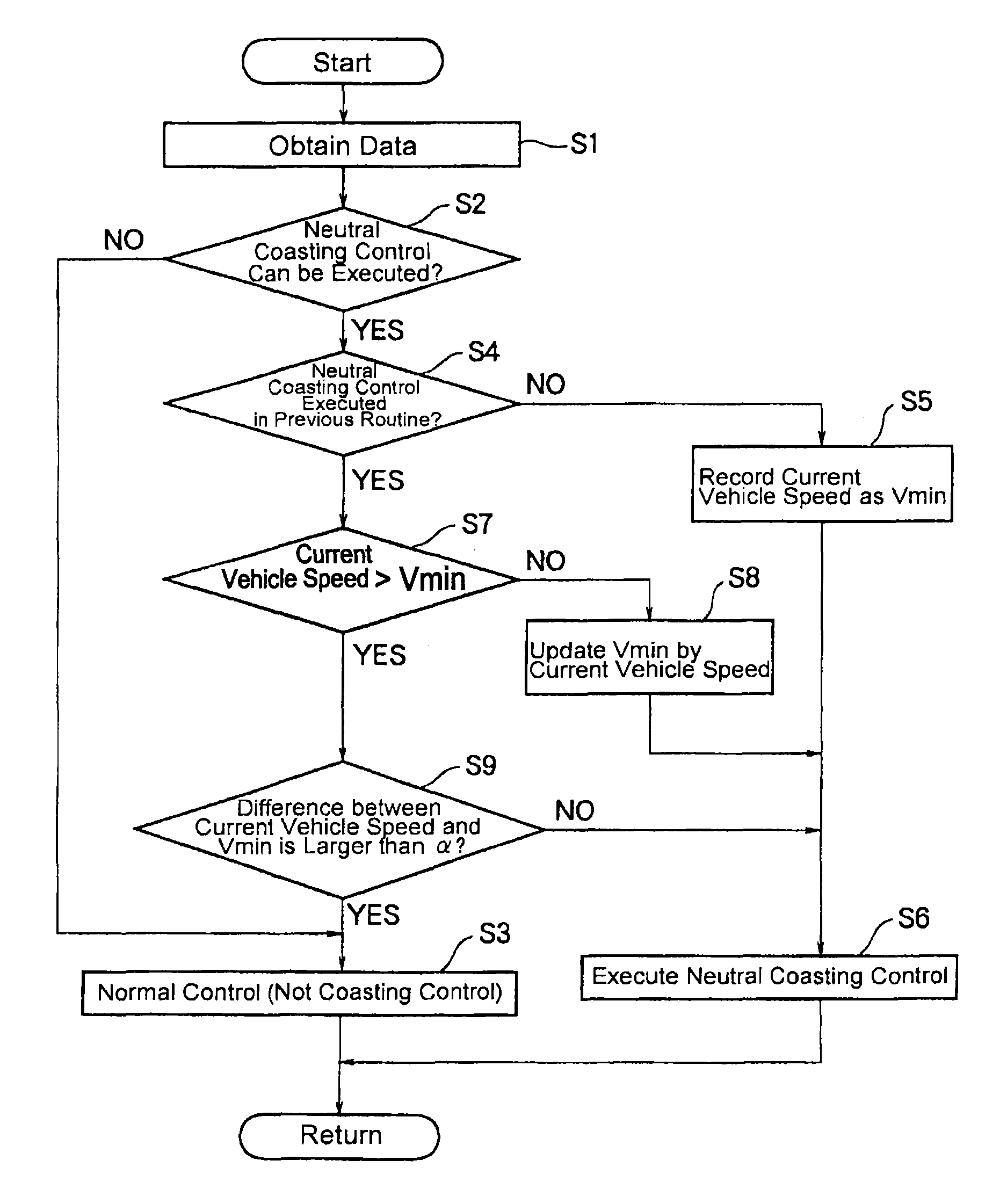
[0025]Next, the present invention will be explained in more detail with reference to the accompanying drawings. FIG. 1 shows a drive line and a control line of the vehicle to which the control system of the present invention is applied. As shown in FIG. 1, the vehicle Ve is comprised of an engine 1, and an automatic transmission 3 connected to an output side of the engine 1 to transmit a power of the engine 1 to drive wheels 2. Specifically, the automatic transmission 3 is disposed on the output side of the engine 1, and an output shaft 3a of the automatic transmission 3 is connected to the drive wheels 2 to transmit power therebetween through a propeller shaft 4, a differential gear 5 and a drive shaft 6. Thus, FIG. 1 shows an example of rear-drive layout of the vehicle Ve in which the engine 1 is connected to the rear drive wheels 2 through the propeller shaft 4. However, the control system of the present invention may also be applied to a front drive vehicle and a four-wheel dri...


PUM


Abstract

A vehicle control system is provided. The vehicle control system is applied to a vehicle having a clutch device to selectively connect and disconnect a power transmission route between a prime mover and drive wheels, and configured to disconnect the power transmission route during running to allow the vehicle to coast. The vehicle control system is comprised of: a vehicle speed detection means; an execution means that executes a coasting control when an operating amount of an accelerator is reduced to be smaller than a predetermined value during running, by bringing the clutch device into disengagement to disconnect the power transmission route so as to allow the vehicle to coast; an updating means that updates a lowest speed of the vehicle during execution of the coasting control; and a termination means that terminates the coasting control by bringing the clutch device into engagement to connect the power transmission route, when a difference between a current vehicle speed and the latest lowest vehicle speed exceeds a predetermined value.

Description

TECHNICAL FIELD[0001]The present invention relates to a control system for a vehicle that is provided with a clutch device for selectively connect and disconnect a prime mover to / from drive wheels through a power transmission route, and that is allowed to coast by bringing the clutch device into disengagement.BACKGROUND ART[0002]In order to improve fuel economy, a fuel cut-off control for stopping fuel supply to an engine during running, and a coasting control for coasting the vehicle by disconnecting the engine from a drive line during running have been employed in recent years. Specifically, the fuel cut-off is carried out to stop fuel supply to the engine given that an accelerator is returned to close an accelerator valve completely, and that an engine speed is higher than an idling speed so that a vehicle speed is higher than a predetermined speed. Under the fuel cut-off control, although the combustion of fuel in the engine is stopped, the engine is still rotating by a torque f...

Claims


Application Information

Patent Timeline
Patent Type & Authority Patents(United States)
IPC IPC(8): B60W30/18F16D48/06B60W10/06B60W10/02
CPCB60W30/18072B60W10/02B60W10/06F16D48/06B60W2030/1809F16D2500/1107F16D2500/3108F16D2500/3127F16D2500/3144F16D2500/3161B60W2520/10B60W2540/10F16D2500/10412F16D2500/3067F16D2500/3109F16D2500/3124F16D2500/31453F16D2500/50825F16D2500/5085F16D2500/7027Y02T10/60
Inventor KIM, JONGGAPSHONO, SHOICHIMOTOZONO, YOSHIKAZU
Owner TOYOTA JIDOSHA KK
Learn More