Gas chromatography-mass spectrometry method and gas chromatography-mass spectrometry apparatus therefor having a capture and release device

a gas chromatography and mass spectrometry technology, applied in mass spectrometers, separation processes, instruments, etc., can solve the problems of increasing cost, inconvenience for users, and the number of drawbacks of conventional gc-ms apparatus

Active Publication Date: 2016-01-05
CHINA TOBACCO FUJIAN IND
View PDF6 Cites 10 Cited by
  • Summary
  • Abstract
  • Description
  • Claims
  • Application Information

AI Technical Summary

Benefits of technology

[0007]It is therefore one object of the invention to provide a method of operating a capture and release device with a switching valve to a gas chromatography-mass spectrometry comprising the steps of: installing a sample injector; installing a heart-cutting unit downstream of the sample injector; installing a first capillary column to connect the sample injector and the heart-cutting unit; connecting a switching valve downstream to the heart-cutting unit via a first interconnecting column; installing a capture and release device downstream to the heart-cutting unit, the capture and release device being able to capture the elution co-eluted from the heart-cutting unit via a cooling unit as well as release the elution via a heating unit; connecting the capture and release device to the switching valve via a second capillary column; connecting the switching valve to a mass spectrometer (MS) via a second interconnecting column; rotating the switching valve to either (a) connect the first and second interconnecting columns, or (b) connect the second capillary column and the second interconnecting column; injecting the sample gas into the first capillary column for preliminary separation via the sample injector; by setting a time slot and carrier gas pressure of the heart-cutting unit, while causing fractions of simple compounds to be cut out and travel to the MS via the first interconnecting column, the switching valve and the second interconnecting column to result in a quantitative and qualitative analysis, causing fractions of complex compounds to be cut out and travel to the capture and release device to be captured via a cooling unit; after the analysis for the simple compounds is finished in MS, causing complex compounds to be released from the capture and release device via a heating unit and travel to the second capillary column for further separation; sending the compounds from the second capillary column to the MS for analysis via the valve and the second interconnecting column to result in a quantitative and qualitative analysis.

Problems solved by technology

However, a number of drawbacks have been found in the conventional GC-MS apparatus.
The simple compounds detected by the detector FID or NPD from a conventional GC-MS can only be able to be resulted in a quantitative analysis while no qualitative analysis as regards the name, structure, CAS No., etc. of such simple compounds may be concluded, thus causing inconvenience to the user.
Adding another MS to the GC-MS device can solve the problem but it will increase cost.

Method used


Image

  • Gas chromatography-mass spectrometry method and gas chromatography-mass spectrometry apparatus therefor having a capture and release device
  • Gas chromatography-mass spectrometry method and gas chromatography-mass spectrometry apparatus therefor having a capture and release device

Examples


embodiment i

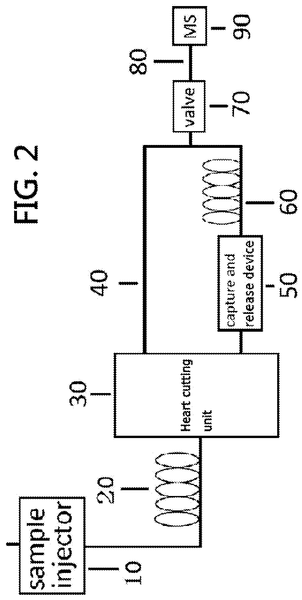
[0018]First, sample chemical compounds are carried through the sample injector 10 by carrier gas prior to be sent into the first capillary column 20 for preliminary separation; by setting a time slot and carrier gas pressure of the heart-cutting unit 30, while causing fractions of simple compounds cut from the heart-cutting unit 30 to travel to the MS 90 via the first interconnecting column 40, the switching valve 70 and the second interconnecting column 80 to result in a quantitative and qualitative analysis, fractions of complex compounds cut from the heart-cutting unit 30 are sent to the capture and release device 50 to be captured via a cooling unit. Liquid nitrogen employed by the capture and release device 50 as cooling medium cools gaseous nitrogen which is in turn sprayed onto the capture unit of the capture and release device 50. The capture unit of the capture and release device 50 thus captures the complex compounds cut from the heart-cutting unit 30. After the analysis f...

embodiment ii

[0022]First, sample chemical compounds are carried through the sample injector 10 by carrier gas prior to be sent into the first capillary column 20 for preliminary separation; by setting a time slot and carrier gas pressure of the heart-cutting unit 30, while causing fractions of simple compounds cut from the heart-cutting unit 30 to travel to the MS 90 via the first interconnecting column 40, the switching valve 70 and the second interconnecting column 80 to result in a quantitative and qualitative analysis, fractions of complex compounds cut from the heart-cutting unit 30 are sent to the capture and release device 50 to be captured via a cooling unit. Liquid nitrogen employed by the capture and release device 50 as cooling medium surrounds and cools the capture unit. The capture unit of the capture and release device 50 thus captures the complex compounds cut from the heart-cutting unit 30. After the analysis for the simple compounds is finished in MS 90, by activating an electri...

embodiment iii

[0026]First, sample chemical compounds are carried through the sample injector 10 by carrier gas prior to be sent into the first capillary column 20 for preliminary separation; by setting a time slot and carrier gas pressure of the heart-cutting unit 30, while causing fractions of simple compounds cut from the heart-cutting unit 30 to travel to the MS 90 via the first interconnecting column 40, the switching valve 70 and the second interconnecting column 80 to result in a quantitative and qualitative analysis, fractions of complex compounds cut from the heart-cutting unit 30 are sent to the capture and release device 50 to be captured via a cooling unit. Liquid nitrogen employed by the capture and release device 50 as cooling medium cools gaseous nitrogen which is in turn sprayed onto the capture unit of the capture and release device 50. The capture unit of the capture and release device 50 thus captures the complex compounds cut from the heart-cutting unit 30. After the analysis f...


PUM

PropertyMeasurementUnit
gas chromatographyaaaaaaaaaa
mass spectrometryaaaaaaaaaa
gas chromatography-aaaaaaaaaa

Abstract

A GC-MS method is provided with installing a sample injector; installing a heart-cutting unit; installing a first capillary column; connecting a switching valve to the heart-cutting unit; installing a capture and release device to the heart-cutting unit; connecting the capture and release device to the switching valve; connecting the switching valve to an MS; rotating the switching valve to either connect the first and second interconnecting columns, or connect the second capillary column and the second interconnecting column; injecting the sample gas into the first capillary column; by setting a time slot and carrier gas pressure of the heart-cutting unit, while causing fractions of simple compounds to be cut out and travel to the MS, causing fractions of complex compounds to be cut out; after the simple compounds finished in MS, causing complex compounds to be released from the capture and release device; and sending the compounds.

Description

BACKGROUND OF THE INVENTION[0001]1. Field of the Invention[0002]The invention relates to gas chromatography-mass spectrometry (GC-MS) instrument and more particularly to a GC-MS method and a GC-MS apparatus therefor, the GC-MS apparatus having a capture and release device.[0003]2. Description of Related Art[0004]A conventional gas chromatography-mass spectrometry (GC-MS) apparatus is shown in FIG. 1 and comprises a sample injector 1, a heart-cutting unit 3 for separating gaseous compounds carried by carrier gas from the sample injector 1 into different fractions, a first capillary column 2 interconnecting the sample injector 1 and the heart-cutting unit 3, a flame ionization detector (FID) 7, an interconnecting column 4 interconnecting the FID 7 and the heart-cutting unit 3, a mass spectrometer (MS) 6, and a second capillary column 5 interconnecting the heart-cutting unit 3 and the MS 6. The FID 7 can be replaced with nitrogen-phosphorous detector (NPD) or one of similar detectors.[...

Claims


Application Information

Patent Timeline
Patent Type & Authority Patents(United States)
IPC IPC(8): H01J49/26G01N30/46G01N30/72
CPCG01N30/461G01N30/7206
Inventor LU, HONGLIANGLIN, KAIYU, JINGCHEN, QUN
Owner CHINA TOBACCO FUJIAN IND
Why Eureka
Try Eureka