
Illumination of optical analytical devices

a technology of optical analytical devices and optical cores, which is applied in the direction of optical fibers with polarisation, fluorescence/phosphorescence, instruments, etc., can solve the problems of reducing the signal to noise ratio resulting from either or both lower signals, increasing the difficulty of multiplexing, and reducing the cross-sectional area of the optical core, so as to reduce the width of the optical core and reduce the cross-sectional area. , the effect of decreasing the width of the optical

Active Publication Date: 2015-12-29
PACIFIC BIOSCIENCES
View PDF158 Cites 60 Cited by
  • Summary
  • Abstract
  • Description
  • Claims
  • Application Information

AI Technical Summary

Benefits of technology

[0013]In some embodiments, the cross-sectional area of the optical core is decreased by adiabatic tapers.
[0014]In some embodiments, the thickness of the optical core is maintained, and the cross-sectional area is decreased by decreasing the width of the optical core. In preferred embodiments, the optical energy is transverse electric polarized light.
[0015]In some embodiments, the width of the optical core is maintained, and the cross-sectional area is decreased by decreasing the thickness of the optical core. In preferred embodiments, the optical energy is transverse magnetic polarized light.

Problems solved by technology

In optical analyses, increasing multiplex often poses increased difficulties, as it may require more complex optical systems, increased illumination or detection capabilities, and new reaction containment strategies.
In some cases, systems seek to increase multiplex by many fold, and even orders of magnitude, which further implicate these considerations Likewise, in certain cases, the analytical environment for which the systems are to be used is so highly sensitive that variations among different analyses in a given system may not be tolerable.
These goals are often at odds with a brute force approach of simply making systems bigger and of higher power, as such steps often give rise to even greater consequences, e.g., in inter reaction cross-talk, decreased signal to noise ratios resulting from either or both of lower signal and higher noise, and the like.
Such systems are typically complex and costly and tend to have significant space requirements.

Method used


Image

  • Illumination of optical analytical devices
  • Illumination of optical analytical devices
  • Illumination of optical analytical devices

Examples


Embodiment Construction

Integrated Optical Detection Devices

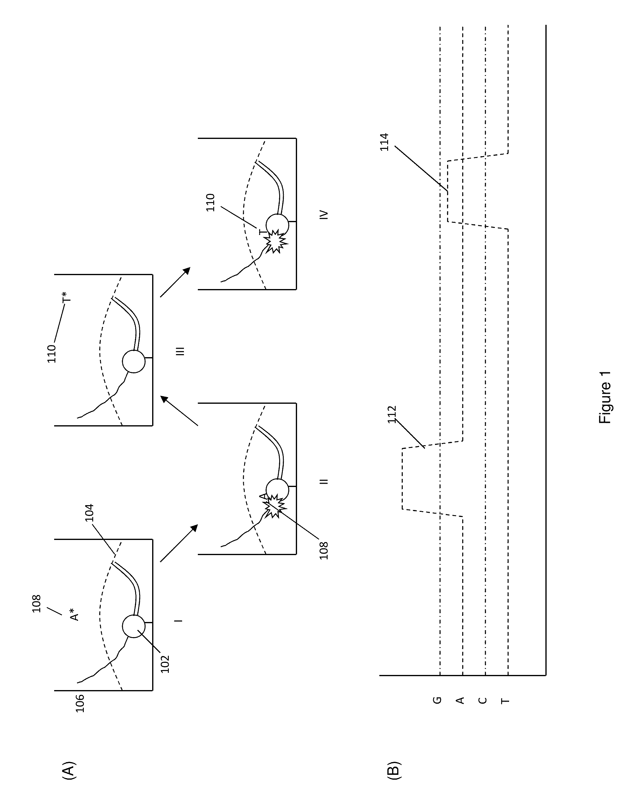
[0039]Multiplexed optical analytical systems are used in a wide variety of different applications. Such applications can include the analysis of single molecules, and can involve observing, for example, single biomolecules in real time as they carry out reactions. For ease of discussion, such multiplexed systems are discussed herein in terms of a preferred application: the analysis of nucleic acid sequence information, and particularly, single molecule nucleic acid sequence analysis. Although described in terms of a particular application, it should be appreciated that the applications for the devices and systems described herein are of broader application.

[0040]In the context of single molecule nucleic acid sequencing analyses, a single immobilized nucleic acid synthesis complex, comprising a polymerase enzyme, a template nucleic acid, whose sequence is being elucidated, and a primer sequence that is complementary to a portion of the template seq...


PUM

PropertyMeasurementUnit
thicknessaaaaaaaaaa
thicknessaaaaaaaaaa
diameteraaaaaaaaaa

Abstract

Optical analytical devices and their methods of use are provided. The devices are useful in the analysis of highly multiplexed optical reactions in large numbers at high densities, including biochemical reactions, such as nucleic acid sequencing reactions. The devices include optical waveguides for illumination of the optical reactions. The devices further provide for the efficient coupling of optical excitation energy from the waveguides to the optical reactions. Optical signals emitted from the reactions can thus be measured with high sensitivity and discrimination using features such as spectra, amplitude, and time resolution, or combinations thereof. The devices of the invention are well suited for miniaturization and high throughput.

Description

CROSS-REFERENCE TO RELATED APPLICATION[0001]This application claims the benefit of U.S. Provisional Application No. 61 / 738,637, filed on Dec. 18, 2012, the disclosure of which is incorporated herein by reference in its entirety.BACKGROUND OF THE INVENTION[0002]In analytical systems, the ability to increase the number of analyses being carried out at any given time by a given system has been a key component to increasing the utility and extending the lifespan of such systems. In particular, by increasing the multiplex factor of analyses with a given system, one can increase the overall throughput of the system, thereby increasing its usefulness while decreasing the costs associated with that use.[0003]In optical analyses, increasing multiplex often poses increased difficulties, as it may require more complex optical systems, increased illumination or detection capabilities, and new reaction containment strategies. In some cases, systems seek to increase multiplex by many fold, and ev...

Claims


Application Information

Patent Timeline
Patent Type & Authority Patents(United States)
IPC IPC(8): G02B6/024G02B6/10G01N21/64G02B6/12
CPCG02B6/024G02B6/12004G02B6/10G01N21/648B82Y15/00B82Y20/00G01N21/7703C12Q1/6874G01N2021/6441G01N21/6454G01N21/253G01N21/6452G01N33/54373G02F1/365G01N21/6486G02B6/0016G02B6/122G02B23/2461
Inventor GROT, ANNETTEWANG, SHANGCALLEBAUT, HANSLUNDQUIST, PAULTURNER, STEPHEN
Owner PACIFIC BIOSCIENCES
Learn More