
Fuel nozzle for reducing modal coupling of combustion dynamics

a technology of modal coupling and fuel nozzle, which is applied in the direction of combustion types, machines/engines, lighting and heating apparatus, etc., can solve the problems of reducing the useful life of one or more combustor and/or downstream components

Active Publication Date: 2015-12-22
GENERAL ELECTRIC CO
View PDF17 Cites 5 Cited by
  • Summary
  • Abstract
  • Description
  • Claims
  • Application Information

AI Technical Summary

Benefits of technology

This patent describes a new fuel nozzle design for gas turbines, which includes a center body and a shroud with several helical passages around it. Each helical passage has a different fuel port position and convective time. This design allows for improved fuel mixing and reduced emissions during combustion. Overall, this patent provides an improved fuel nozzle that enhances gas turbine performance.

Problems solved by technology

The resulting combustion dynamics may reduce the useful life of one or more combustor and / or downstream components.

Method used


Image

  • Fuel nozzle for reducing modal coupling of combustion dynamics
  • Fuel nozzle for reducing modal coupling of combustion dynamics
  • Fuel nozzle for reducing modal coupling of combustion dynamics

Examples


Embodiment Construction

[0016]Reference will now be made in detail to present embodiments of the invention, one or more examples of which are illustrated in the accompanying drawings. The detailed description uses numerical and letter designations to refer to features in the drawings. Like or similar designations in the drawings and description have been used to refer to like or similar parts of the invention. As used herein, the terms “first,”“second,” and “third” may be used interchangeably to distinguish one component from another and are not intended to signify location or importance of the individual components. The terms “upstream,”“downstream,”“radially,” and “axially” refer to the relative direction with respect to fluid flow in a fluid pathway. For example, “upstream” refers to the direction from which the fluid flows, and “downstream” refers to the direction to which the fluid flows. Similarly, “radially” refers to the relative direction substantially perpendicular to the fluid flow, and “axially...


PUM


Abstract

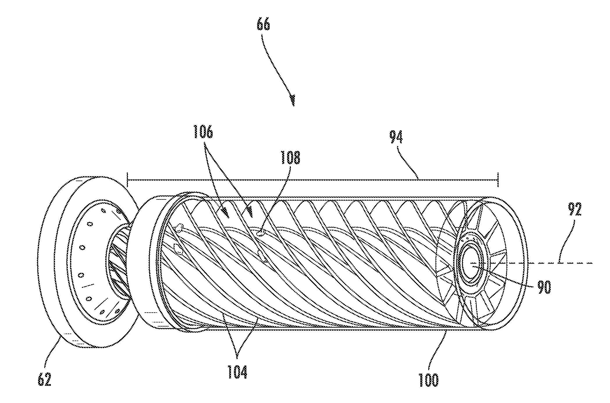
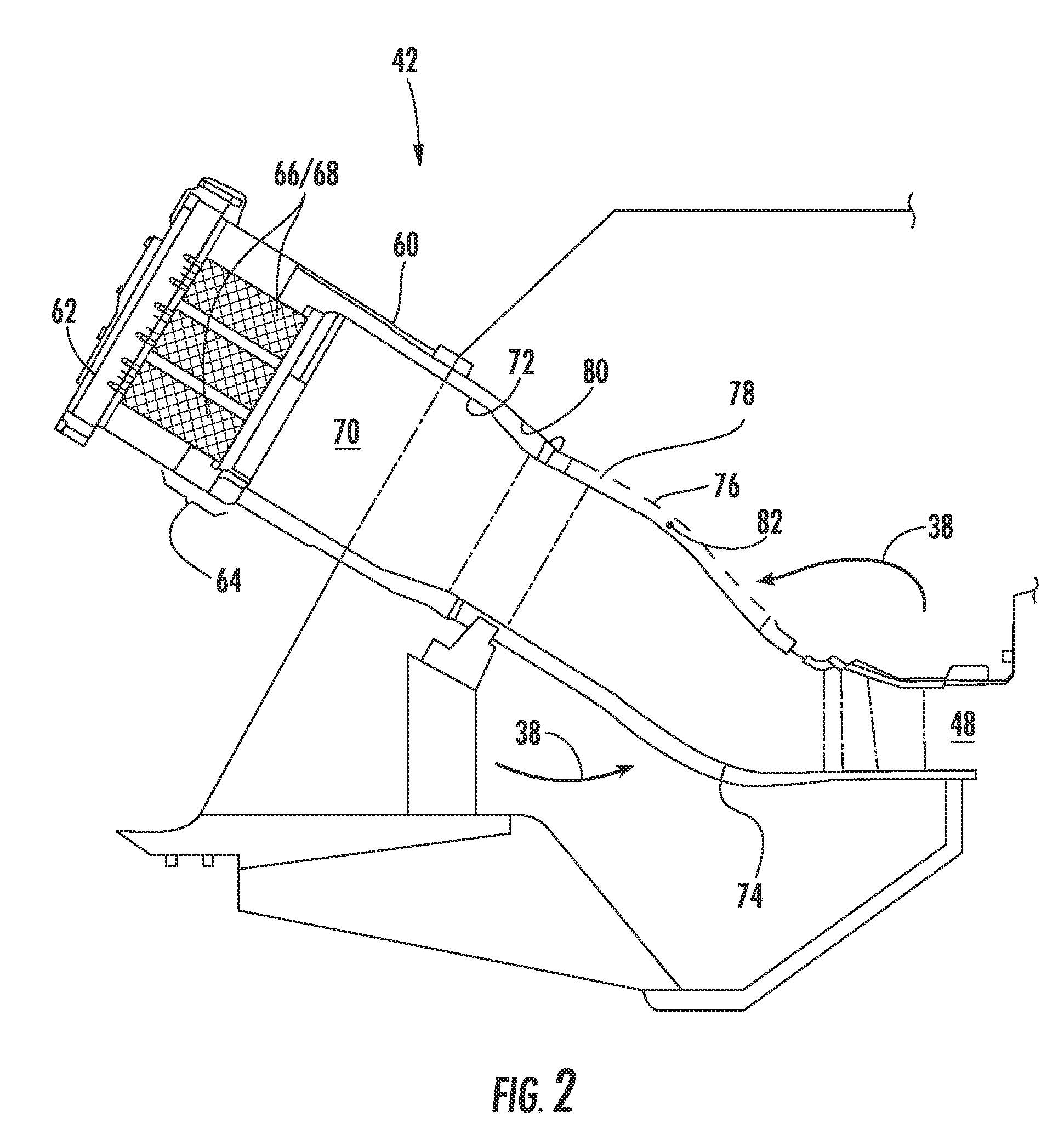
A fuel nozzle includes a center body that extends axially along an axial centerline for a length. A shroud circumferentially surrounds the center body for at least a portion of the length of the center body. A plurality of helical passages circumferentially surround the center body along at least a portion of the length of the center body, and a fuel port in each helical passage has a different convective time.

Description

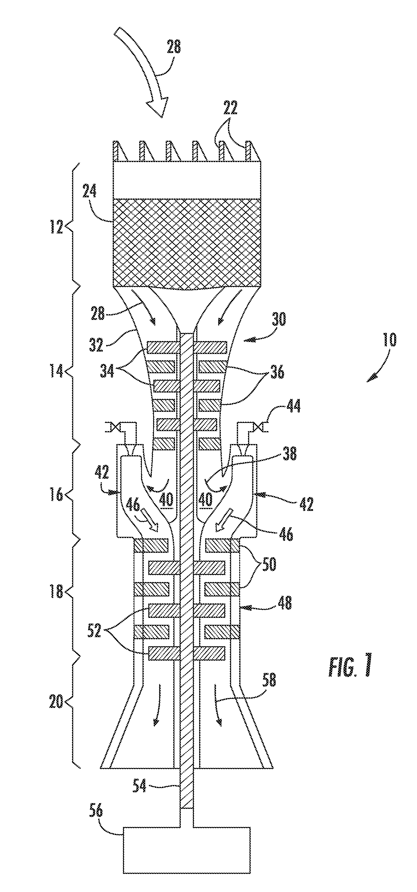
FIELD OF THE INVENTION[0001]The present invention generally involves a fuel nozzle for reducing modal coupling of combustion dynamics. In particular embodiments, the fuel nozzle and method may be incorporated into a gas turbine or other turbomachine.BACKGROUND OF THE INVENTION[0002]Combustors are commonly used in industrial and commercial operations to ignite fuel to produce combustion gases having a high temperature and pressure. For example, gas turbines and other turbomachines typically include one or more combustors to generate power or thrust. A typical gas turbine used to generate electrical power includes an axial compressor at the front, multiple combustors around the middle, and a turbine at the rear. Ambient air enters the compressor as a working fluid, and the compressor progressively imparts kinetic energy to the working fluid to produce a compressed working fluid at a highly energized state. The compressed working fluid exits the compressor and flows through one or more...

Claims


Application Information

Patent Timeline
Patent Type & Authority Patents(United States)
IPC IPC(8): F02C1/00F02C7/24F23R3/28
CPCF02C7/24F23R3/28F23R2900/00014F23R3/286F23D9/00F23D14/045F23D14/80
Inventor BOARDMAN, GREGORY ALLENWESTMORELAND, III, JAMES HAROLDCROTHERS, SARAH LORICHILA, RONALD JAMES
Owner GENERAL ELECTRIC CO
Learn More