
Temperature compensation method and apparatus for received signal strength indicator

a temperature compensation and signal strength indicator technology, applied in the field of temperature compensation, can solve the problems of increasing hardware complexity and inaccuracy of power measurement, and achieve the effect of improving the accuracy of temperature compensation

Active Publication Date: 2015-12-08
FUJITSU LTD
View PDF5 Cites 0 Cited by
  • Summary
  • Abstract
  • Description
  • Claims
  • Application Information

AI Technical Summary

Benefits of technology

The present invention provides a method and apparatus for compensating for temperature variations in a received signal strength indicator (RSSI) to improve accuracy. This is achieved by measuring the characteristics of the RSSI at three different temperatures and using an interpolation method to compensate for the temperature-dependent characteristics of the RSSI. This method reduces the required storage space and improves the accuracy of temperature compensation compared to existing methods.

Problems solved by technology

However, variation of ambient temperature will have effect on the characteristics of the RSSI, resulting in inaccuracy of the power measurement result.
All of these methods increase the complexity of hardware.

Method used


Image

  • Temperature compensation method and apparatus for received signal strength indicator
  • Temperature compensation method and apparatus for received signal strength indicator
  • Temperature compensation method and apparatus for received signal strength indicator

Examples


embodiment 1

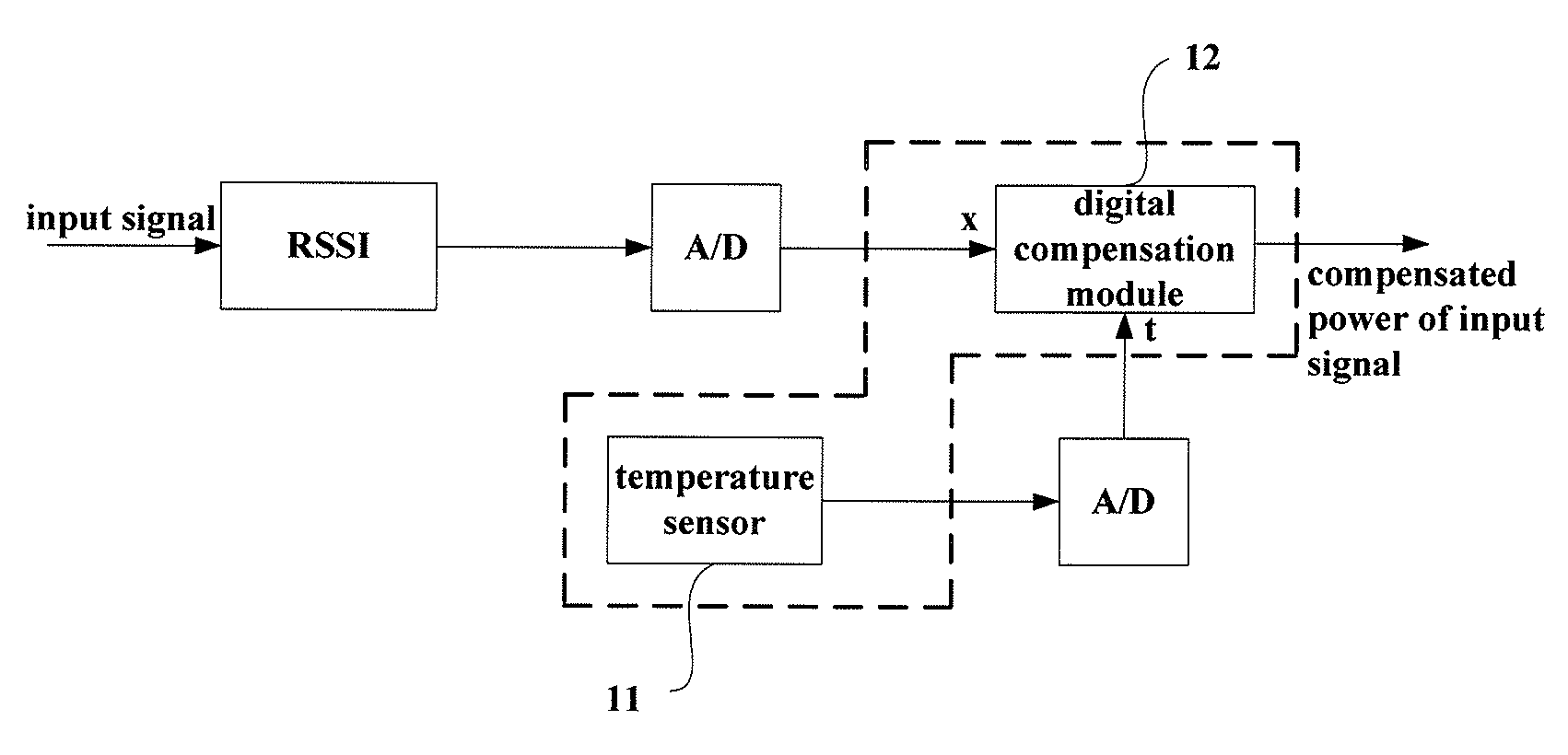
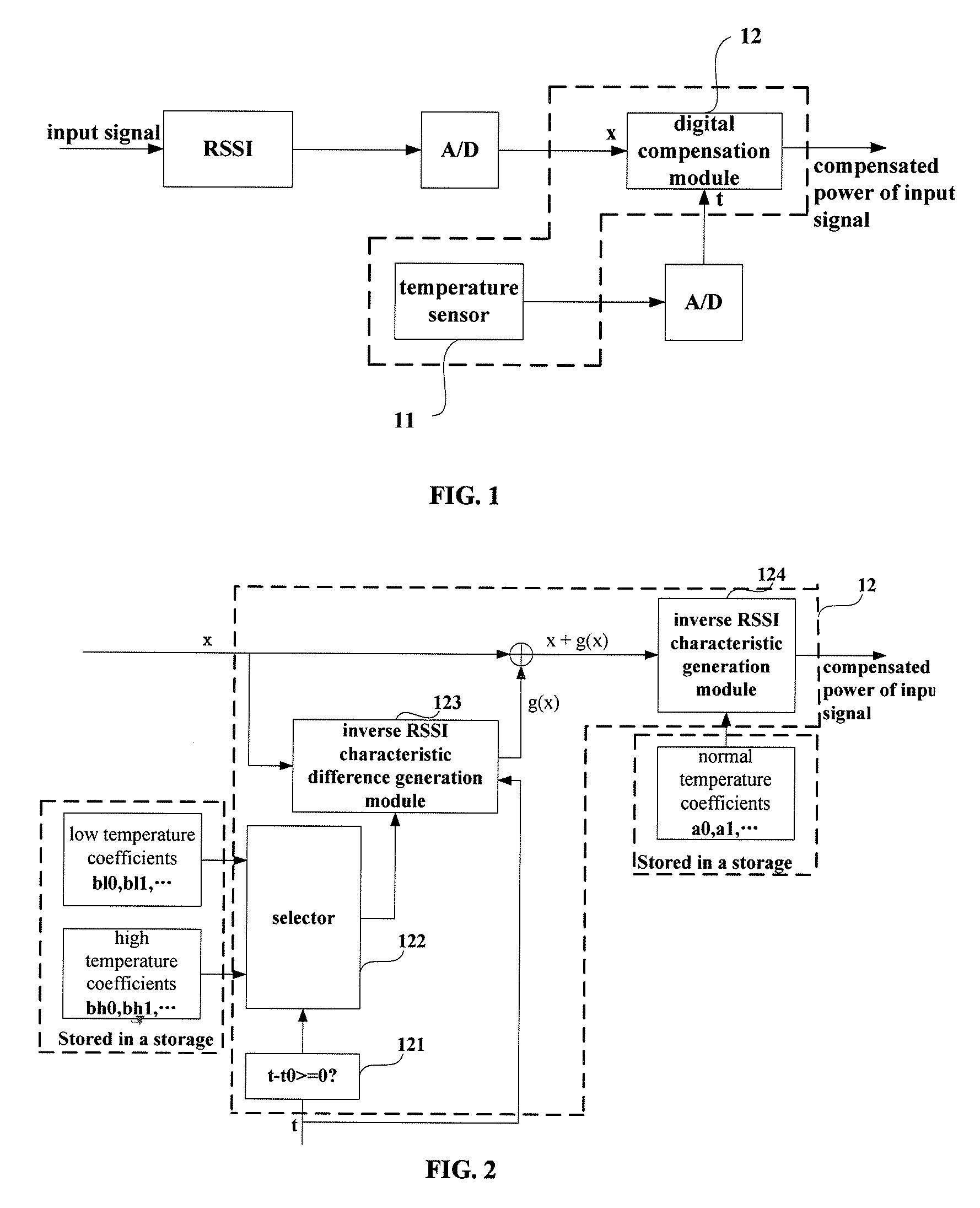
[0034]An embodiment of the present invention provides a temperature compensation apparatus for an RSSI. FIG. 1 is a schematic diagram of the composition of the temperature compensation apparatus. As shown in FIG. 1, the apparatus comprises:

[0035]a temperature sensor 11 configured to measure a current temperature; and

[0036]a digital compensation module 12 configured to select a temperature compensation coefficient from prestored temperature compensation coefficients corresponding to a normal temperature, a low temperature and a high temperature according to the current temperature, and perform temperature compensation on output signals of the RSSI according to the selected temperature compensation coefficient, thereby obtaining power of input signals of the RSSI.

[0037]As shown in FIG. 1, digital signals x are obtained after the output signals of the RSSI are converted by an A / D converter, and are inputted into the digital compensation module 12 thereafter. The temperature sensor 11 (...

embodiment 2

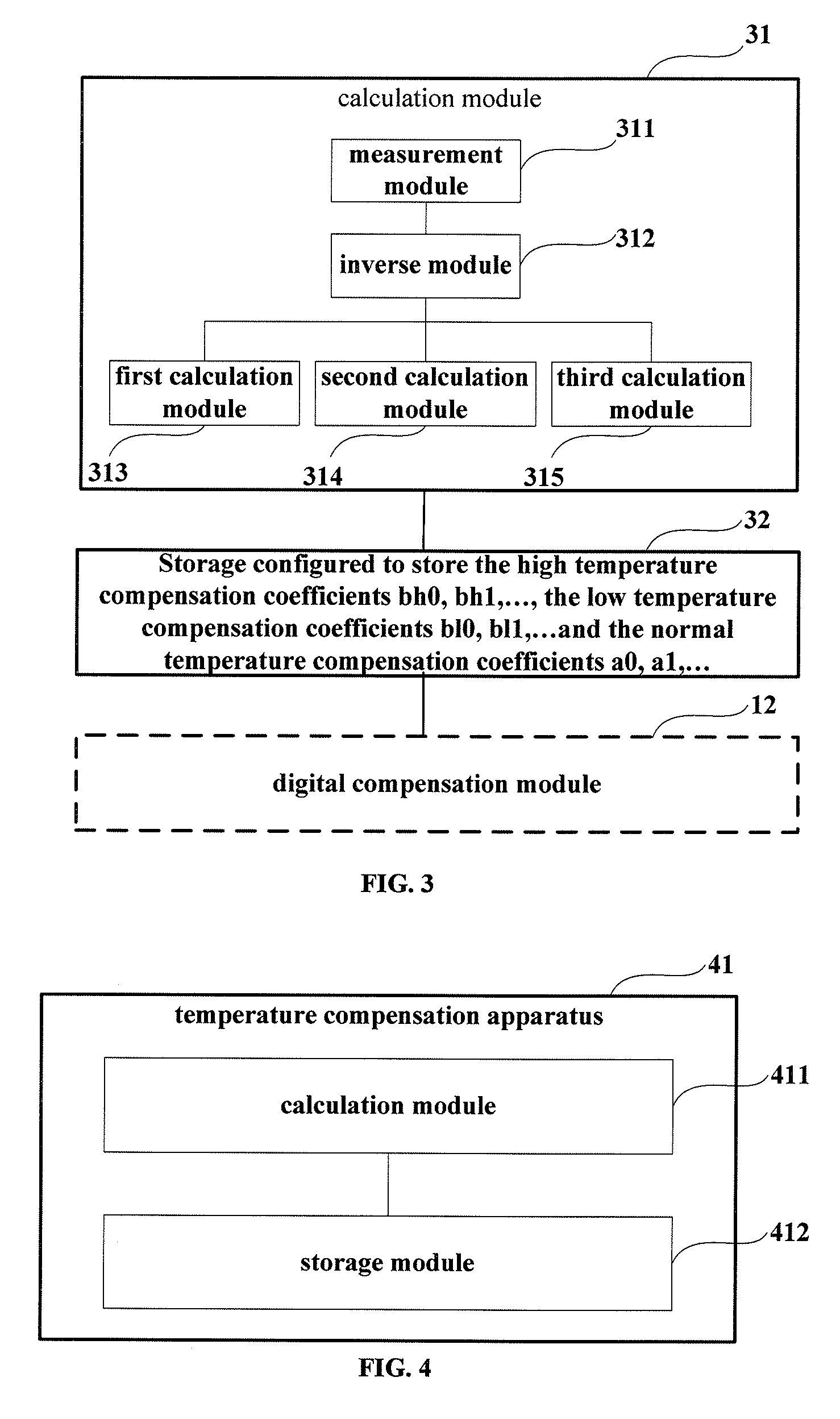
[0065]An embodiment of the present invention further provides electronic equipment. FIG. 4 is a schematic diagram of the composition of the electronic equipment, which uses an RSSI signal for signal power measurement. Referring to FIG. 4, besides the original compositions and functions, the electronic equipment further comprises a temperature compensation apparatus 41 configured to perform temperature compensation on RSSI input signals in measuring the signal power of the electronic equipment.

[0066]In this embodiment, the temperature compensation apparatus 41 comprises a calculation module 411 configured to calculate temperature compensation coefficients and a storage module 412 configured to store the temperature compensation coefficients, and may be realized by the temperature compensation apparatus of Embodiment 1, the contents of which being incorporated herein, which shall not be described herein any further.

[0067]The electronic equipment of this embodiment uses the temperature...

embodiment 3

[0068]An embodiment of the present invention further provides electronic equipment. FIG. 5 is a schematic diagram of the composition of the electronic equipment, which uses an RSSI signal for signal power measurement. Referring to FIG. 5, besides the original compositions and functions, the electronic equipment further comprises a temperature compensation apparatus 51, a calculation module 52 and a storage module 53.

[0069]In this embodiment, the temperature compensation apparatus 51 is configured to perform temperature compensation on RSSI input signals in measuring signal power of the electronic equipment, and may be realized by the temperature compensation apparatus shown in FIG. 2, the contents of which being incorporated herein, which shall not be described herein any further.

[0070]In this embodiment, the calculation module 52 is configured to calculate the normal temperature coefficients, the low temperature coefficients, and the high temperature coefficients, and may be realiz...


PUM


Abstract

Embodiments of the present invention provide a temperature compensation method and apparatus for a received signal strength indicator. The apparatus comprises a temperature sensor configured to measure a current temperature; and a digital compensation module configured to select a temperature compensation coefficient from prestored temperature compensation coefficients corresponding to a normal temperature, a low temperature and a high temperature according to the current temperature, and perform temperature compensation on output signals of the RSSI according to the selected temperature compensation coefficient. With the method and apparatus of the embodiments of the present invention, the accurate power values of the input signals of the RSSI under any temperatures can be obtained by measuring the characteristics of the RSSI under the predefined three temperatures, and using an interpolation method to compensate for the temperature characteristics of the RSSI. In comparison with the relevant art, the size of the storage is decreased and the accuracy of temperature compensation is improved.

Description

CROSS-REFERENCE TO RELATED APPLICATION[0001]This application is based upon and claims the benefit of priority of the Chinese Patent Application No. 201210371377.9, filed Sep. 28, 2012, the disclosure of the prior application of which is hereby incorporated in its entirety by reference.TECHNICAL FIELD[0002]The present invention relates to the field of temperature compensation and, in particular to a temperature compensation method and apparatus for a Received Signal Strength Indicator (RSSI) for compensating for temperature characteristics of the RSSI in using the RSSI for power measurement.BACKGROUND ART[0003]RSSI is widely used in power measurement of signals. However, variation of ambient temperature will have effect on the characteristics of the RSSI, resulting in inaccuracy of the power measurement result. When the ambient temperature varies, temperature characteristics of the RSSI need to be compensated, so as to ensure accuracy of the power measurement result of the RSSI.[0004...

Claims


Application Information

Patent Timeline
Patent Type & Authority Patents(United States)
IPC IPC(8): H04B1/16H04B17/21H04B17/00H04B17/318G01R29/08
CPCH04B17/21H04B17/318
Inventor LI, HUIIWAMATSU, TAKANORIZHOU, JIANMIN
Owner FUJITSU LTD
Learn More