Methods and systems for charging electrical devices via an electrical system

a technology of electrical devices and electrical systems, applied in the integration of power network operation systems, battery/fuel cell control arrangements, transportation and packaging, etc., can solve the problems of increasing the wear and tear of batteries, significant infrastructure-related concerns, and serious challenges in the adoption of bidirectional control

Active Publication Date: 2015-12-08
UNIV OF WASHINGTON CENT FOR COMMERICIALIZATION
View PDF36 Cites 12 Cited by
  • Summary
  • Abstract
  • Description
  • Claims
  • Application Information

AI Technical Summary

Benefits of technology

The patent text discusses the problem of controlling electric vehicles and other electrical devices in an efficient and effective way. While bidirectional control can be beneficial, it faces challenges such as cycling wear on batteries and interconnection issues. As a result, unidirectional control has been developed to address these challenges. However, existing unidirectional control techniques have proven inadequate. The patent proposes a new method for unidirectional control that takes into account factors such as battery state of charge, charging scenario, and profit maximization. The method involves determining the power draw of each electrical device in the system and controlling their power draw based on a schedule. This approach optimizes energy usage and reduces wear and tear on batteries. The patent also discusses the challenges of unidirectional control and proposes solutions to address these challenges.

Problems solved by technology

However, bidirectional control faces serious challenges for its adoption, especially in the short term.
Further, bidirectional power flow gives rise to the need for anti-islanding protection, as well as the need to address numerous other interconnection issues, resulting in significant infrastructure-related concerns.
Further still, bidirectional power flow results in increased cycling wear on batteries and, therefore, decreased lifetimes of batteries.
Such drawbacks of bidirectional control may apply to the aggregation of electrical devices other than electric vehicles.
However, many existing electric vehicles, and electrical devices more generally, can participate in unidirectional energy aggregation without the need for significant modifications to infrastructure, charging stations, or the electrical devices themselves.
Nonetheless, efforts thus far to develop such optimization techniques have proven inadequate.

Method used


Image

  • Methods and systems for charging electrical devices via an electrical system
  • Methods and systems for charging electrical devices via an electrical system
  • Methods and systems for charging electrical devices via an electrical system

Examples


Embodiment Construction

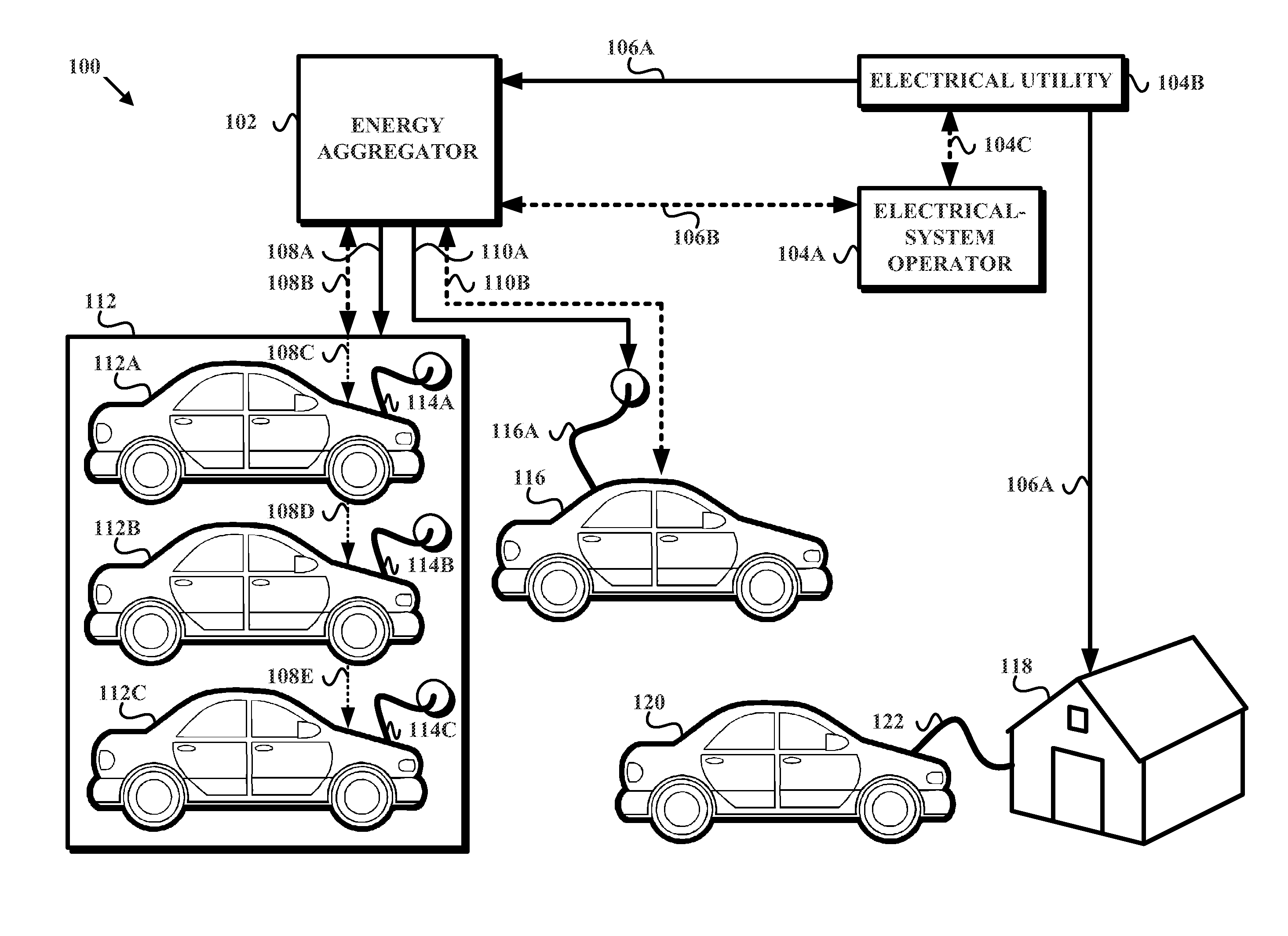
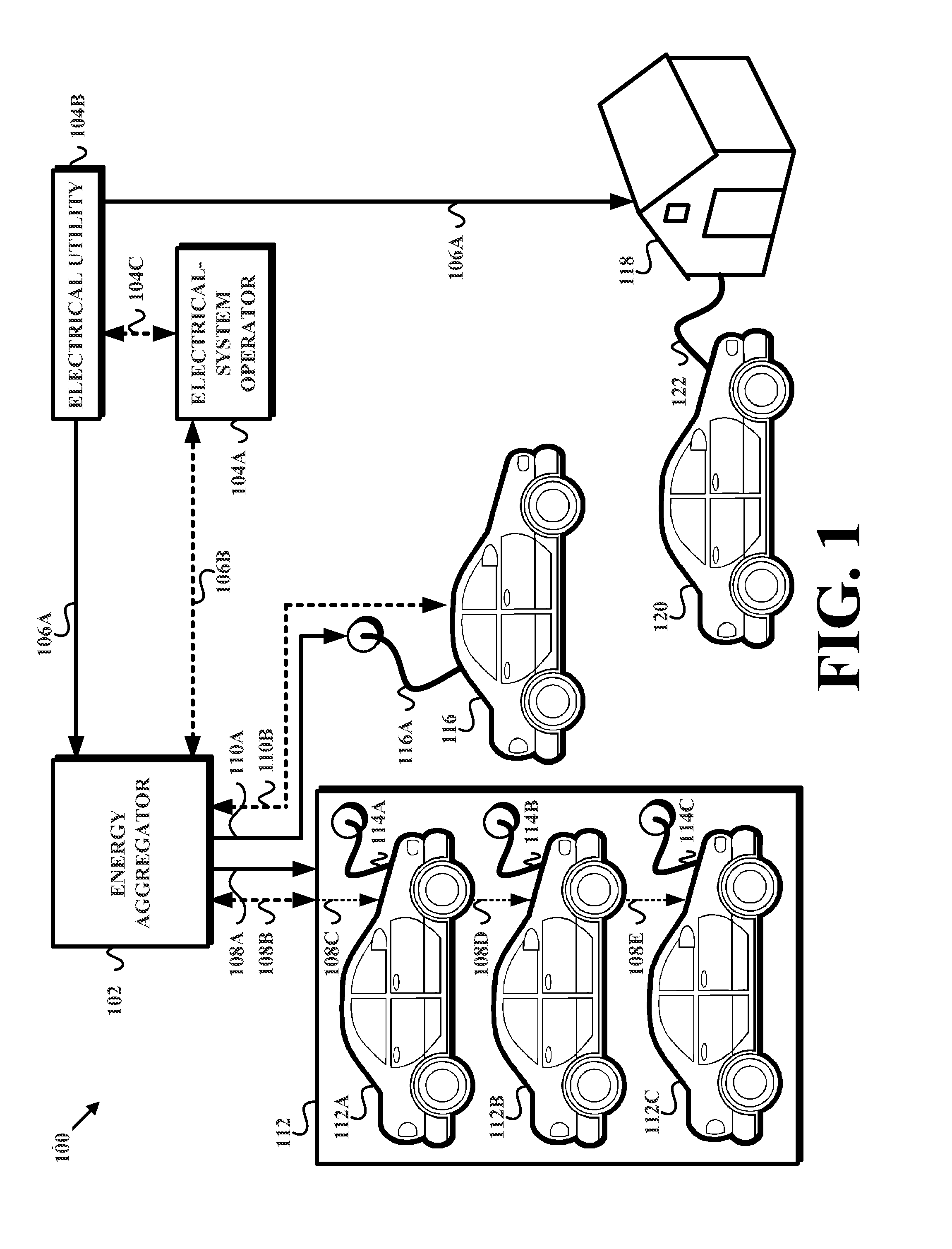
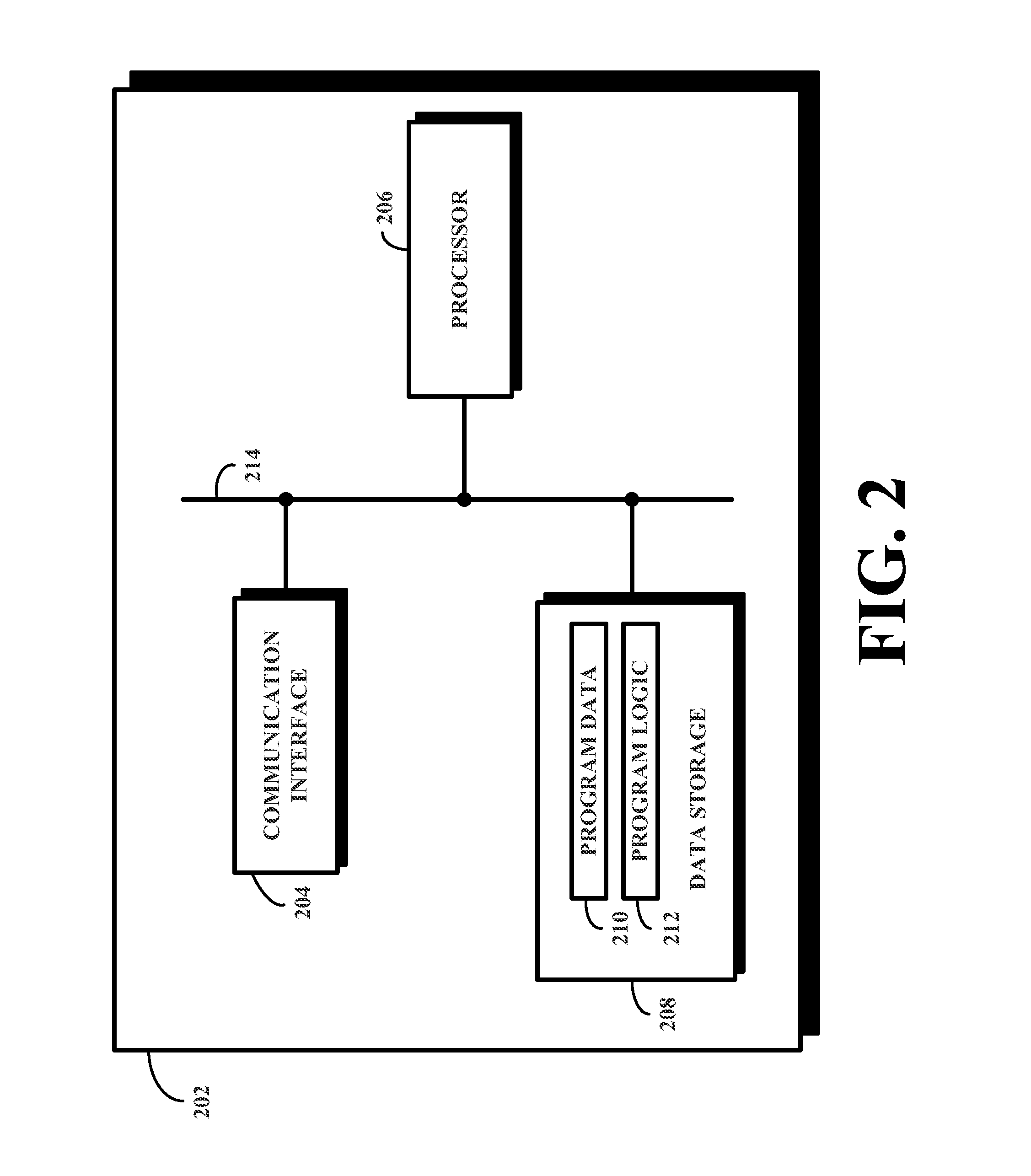
[0025]In the following detailed description, reference is made to the accompanying figures, which form a part thereof. In the figures, similar symbols typically identify similar components, unless context dictates otherwise. The illustrative embodiments described in the detailed description, figures, and claims are not meant to be limiting. Other embodiments may be utilized, and other changes may be made, without departing from the spirit or scope of the subject matter presented herein. It will be readily understood that the aspects of the present disclosure, as generally described herein, and illustrated in the figures, can be arranged, substituted, combined, separated, and designed in a wide variety of different configurations, all of which are contemplated herein.

[0026]Further, certain aspects of the disclosure herein refer to the “optimization,” or some variation thereof, of the power draw of a given electrical device. It should be understood that use of such a term (i.e. “optim...


PUM


Abstract

Disclosed herein are methods, systems, and devices that may be implemented by an energy aggregator to control, or regulate, the electric load placed on an electric grid by an aggregation of electrical devices, such as electric vehicles. Generally, the disclosed methods, and systems may provide for the modulation of the power draw of each electric vehicle around a first power draw, or scheduled power draw. Further, the disclosed methods and systems provide for the determination of a desirable scheduled power draw for a given electric vehicle. In one example, the scheduled power draw may be determined based on, among other things, the amount of time left in a given charging scenario and the state of charge of the given electric vehicle. In another example, the scheduled power draw may be determined based on, among other considerations, a maximization of the profit derived by the energy aggregator for both providing power to an aggregation of electric vehicles and for providing a regulation function to the electrical grid (at the request, for example, of an electrical-system operator).

Description

RELATED APPLICATIONS[0001]This application claims priority to U.S. Provisional Patent Application Ser. No. 61 / 370,776 filed Aug. 4, 2010, entitled Optimal Charging Strategies for Unidirectional Vehicle-to-Grid, which is incorporated herein in its entirety.BACKGROUND[0002]Today, power is typically generated by a given power-generation source (e.g., a coal-, natural gas-, nuclear-, hydro-, or oil-based power plant, and / or, increasingly, some other renewable energy source, such as wind or solar) and then transmitted and distributed throughout a given geographic region via an electrical grid. Entities that generate, transmit, and / or distribute power may be referred to as utilities, while entities that coordinate, control, and / or monitor electricity transmission throughout the electrical grid may be referred to as electrical-system operators (e.g., a regional transmission organization (RTO) or an independent system operator (ISO)). Grids covering large geographic regions, such as the Uni...

Claims


Application Information

Patent Timeline
Patent Type & Authority Patents(United States)
IPC IPC(8): H02J7/00H02J3/14H02J3/00
CPCH02J3/14H02J7/0027Y02T90/168H02J2003/007Y04S10/126B60L11/1844Y02T10/7072Y04S30/14H02J3/008Y02B70/3225Y04S20/222Y04S30/12Y04S40/126B60L53/64B60L53/63B60L58/13H02J2310/64H02J2310/48H02J2310/60H02J13/00024H02J13/00026Y02B90/20Y02E60/00Y02T10/70Y02T90/12Y02T90/167Y04S20/242Y02B70/30Y02T90/14Y04S50/10H02J2203/20Y02T90/16
Inventor SORTOMME, ERIC VESLE
Owner UNIV OF WASHINGTON CENT FOR COMMERICIALIZATION
Why Eureka
Try Eureka