Dynamic lockstep cache memory replacement logic

a memory replacement and dynamic lockstep technology, applied in the direction of memory adressing/allocation/relocation, redundant hardware error correction, instruments, etc., can solve the problems of squandering useful processing cycles, burdening non-critical aspects of data processing applications, and expensive redundancy processors

Active Publication Date: 2015-12-08
NXP USA INC
View PDF18 Cites 1 Cited by
  • Summary
  • Abstract
  • Description
  • Claims
  • Application Information

AI Technical Summary

Problems solved by technology

Unfortunately, providing redundant processors can be expensive and, as a general proposition, not all aspects of a data processing application require such reliability or safety integrity levels.
As a result, non-critical aspects of a data processing application may be burdened by lockstep execution overheads and / or otherwise useful processing cycles may be squandered.

Method used


Image

  • Dynamic lockstep cache memory replacement logic
  • Dynamic lockstep cache memory replacement logic
  • Dynamic lockstep cache memory replacement logic

Examples


implementation example

Cache Storage and Implementation Example

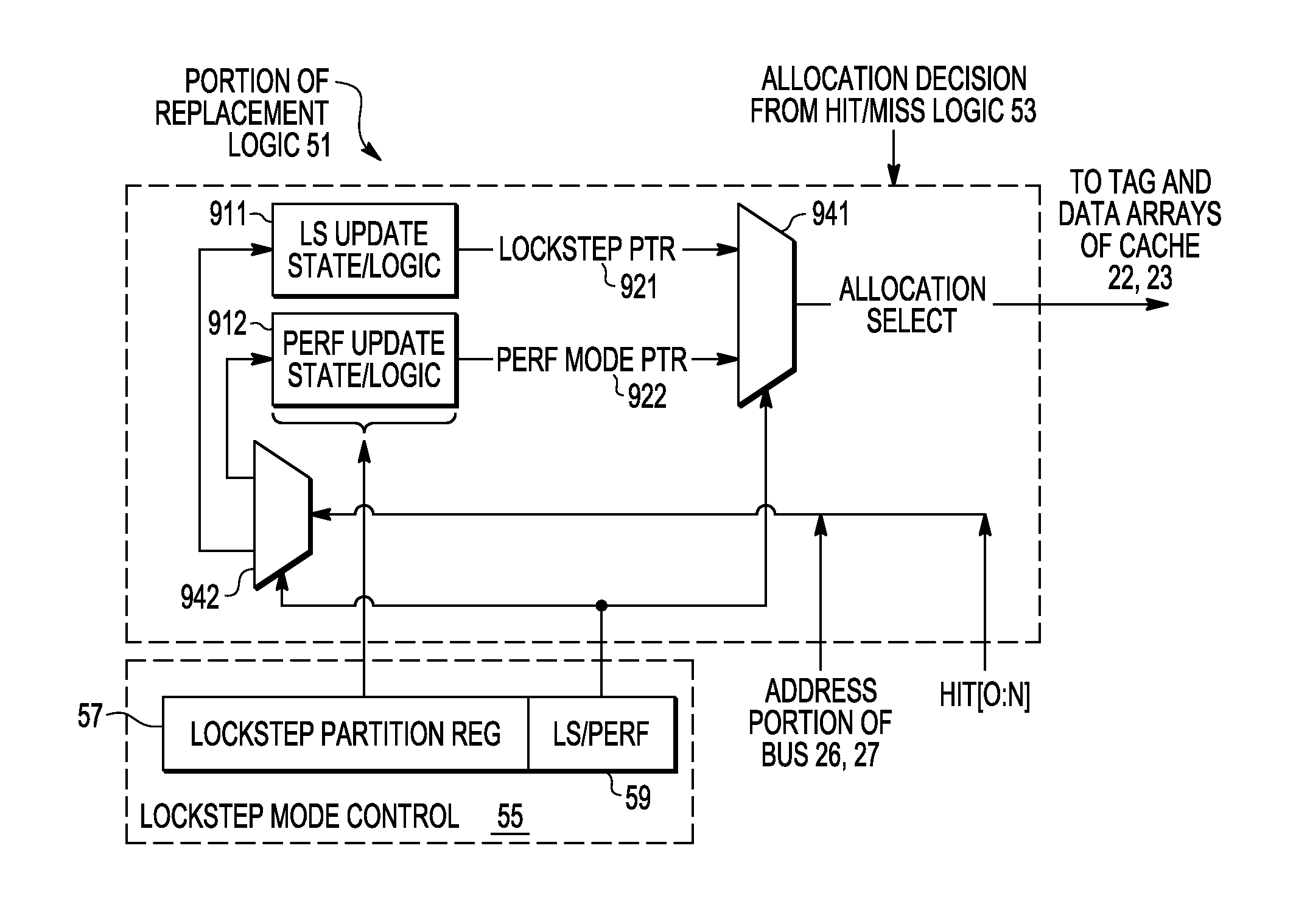
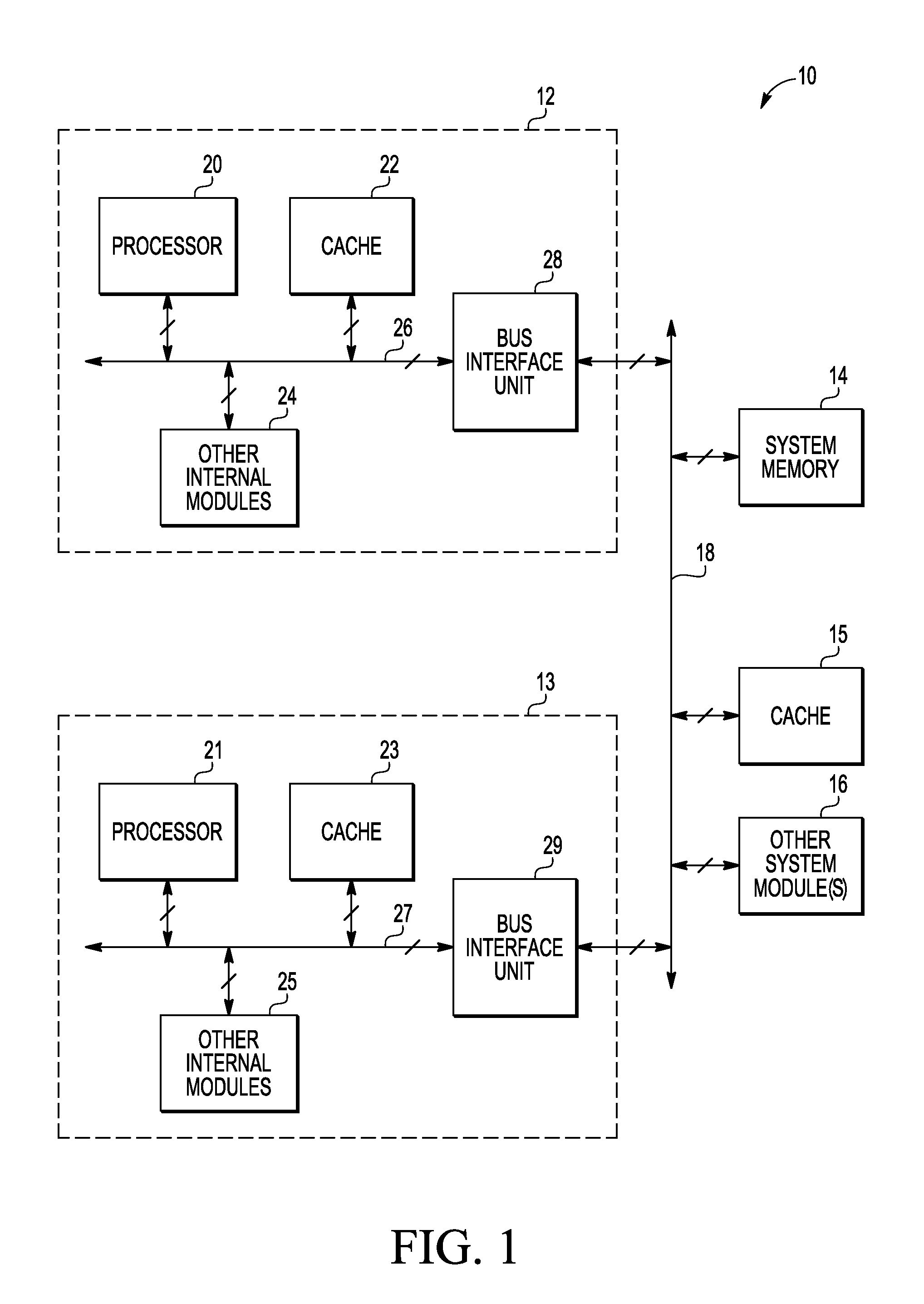
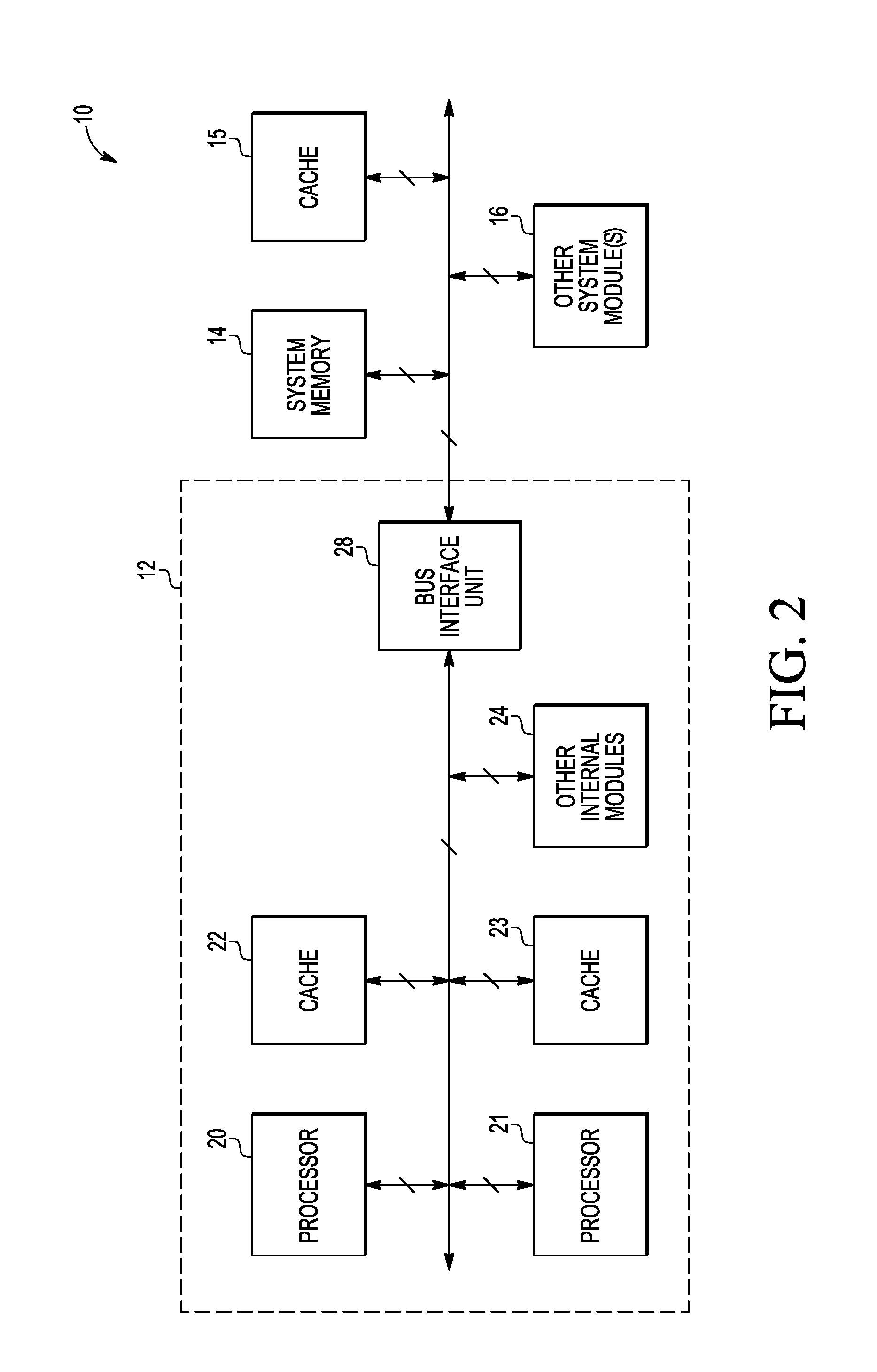
[0042]FIG. 3 depicts portions of one example of an N-way, set-associative cache instance such as illustrated in FIGS. 1 and 2 as cache 22 and / or cache 23. The illustrated cache instance includes cache control logic adapted for dynamic lockstep support in accordance with some embodiments of the present invention. Cache 22, 23 includes a tag memory array for multiple ways 42, 44, 46 . . . 48, data memory array for multiple ways 50, 52, 54 . . . 56, and cache control logic 58. In the illustrated portion of cache 22, 23, lockstep mode control 55 (which may be implemented as one or more control registers of, or accessible to, cache control logic 58) codes or otherwise identifies a current operating mode (e.g., lockstep or performance) together with a current way-denominated partition of the associated cache instance into lockstep ways 81 and performance ways 82.

[0043]An access address 40 is received from an address portion of bus 26 or 27 and has a...


PUM


Abstract

To facilitate dynamic lockstep support, replacement states and / or logic used to select particular cache lines for replacement with new allocations in accord with replacement algorithms or strategies may be enhanced to provide generally independent replacement contexts for use in respective lockstep and performance modes. In some cases, replacement logic that may be otherwise conventional in its selection of cache lines for new allocations in accord with a first-in, first-out (FIFO), round-robin, random, least recently used (LRU), pseudo LRU, or other replacement algorithm / strategy is at least partially replicated to provide lockstep and performance instances that respectively cover lockstep and performance partitions of a cache. In some cases, a unified instance of replacement logic may be reinitialized with appropriate states at (or coincident with) transitions between performance and lockstep modes of operation.

Description

CROSS-REFERENCE TO RELATED APPLICATION(S)[0001]The present application is related to commonly-owned, co-pending U.S. patent application Ser. No. 13 / 090,057, filed on even date herewith, entitled “CACHE MEMORY WITH DYNAMIC LOCKSTEP SUPPORT,” and naming William C. Moyer as inventor, the entirety of which is incorporated herein by reference.BACKGROUND[0002]1. Field[0003]The present invention relates to multiprocessor data processing systems and, more particularly, to cache techniques that facilitate transitioning between lockstep and non-lockstep modes of processor operation.[0004]2. Related Art[0005]In some data processing applications, multiple processor instances are employed to concurrently execute identical code sequences with identical data inputs. Typically, the processors execute in lockstep. Error logic may then detect a difference in execution states of the processors and, based thereon, signal a transient or permanent error in one of the processor instances. For example, in ...

Claims


Application Information

Patent Timeline
Patent Type & Authority Patents(United States)
IPC IPC(8): G06F12/02G06F11/16G06F12/08G06F12/12
CPCG06F11/1658G06F12/0848G06F12/126G06F11/1629G06F2201/845G06F2212/1016G06F2212/1032
Inventor MOYER, WILLIAM C.
Owner NXP USA INC
Why Eureka
Try Eureka