
Method and system for feeding and ventilating with air a plant of an aircraft auxiliary power unit

a technology of auxiliary power units and air intake, which is applied in the direction of machines/engines, mechanical equipment, transportation and packaging, etc., can solve the problems of increasing weight and cost, affecting the effectiveness of ventilation, etc., and achieves the maximum ventilation of auxiliary power units and equipment items

Active Publication Date: 2015-12-08
SAFRAN POWER UNITS
View PDF11 Cites 1 Cited by
  • Summary
  • Abstract
  • Description
  • Claims
  • Application Information

AI Technical Summary

Benefits of technology

The patent describes a system for distributing air and fluid flows in an aircraft engine. This system separates out different air flows, which helps to avoid issues with flow rates. It also eliminates the need for expensive and unreliable internal mobile systems. The system is designed to maximize the ventilation of the engine and its equipment, ensuring optimal performance.

Problems solved by technology

The mounting of the cooler on pipework incorporating the discharger requires complex and bulky sheet metalwork which adversely affects the effectiveness of the ventilation and induces an increase in weight and cost.

Method used


Image

  • Method and system for feeding and ventilating with air a plant of an aircraft auxiliary power unit
  • Method and system for feeding and ventilating with air a plant of an aircraft auxiliary power unit

Examples


Embodiment Construction

[0027]In this description, the “upstream-downstream” qualifier follows the direction defined by the gas flows in the gas generator, the “downstream-upstream” qualifier follows the reverse direction.

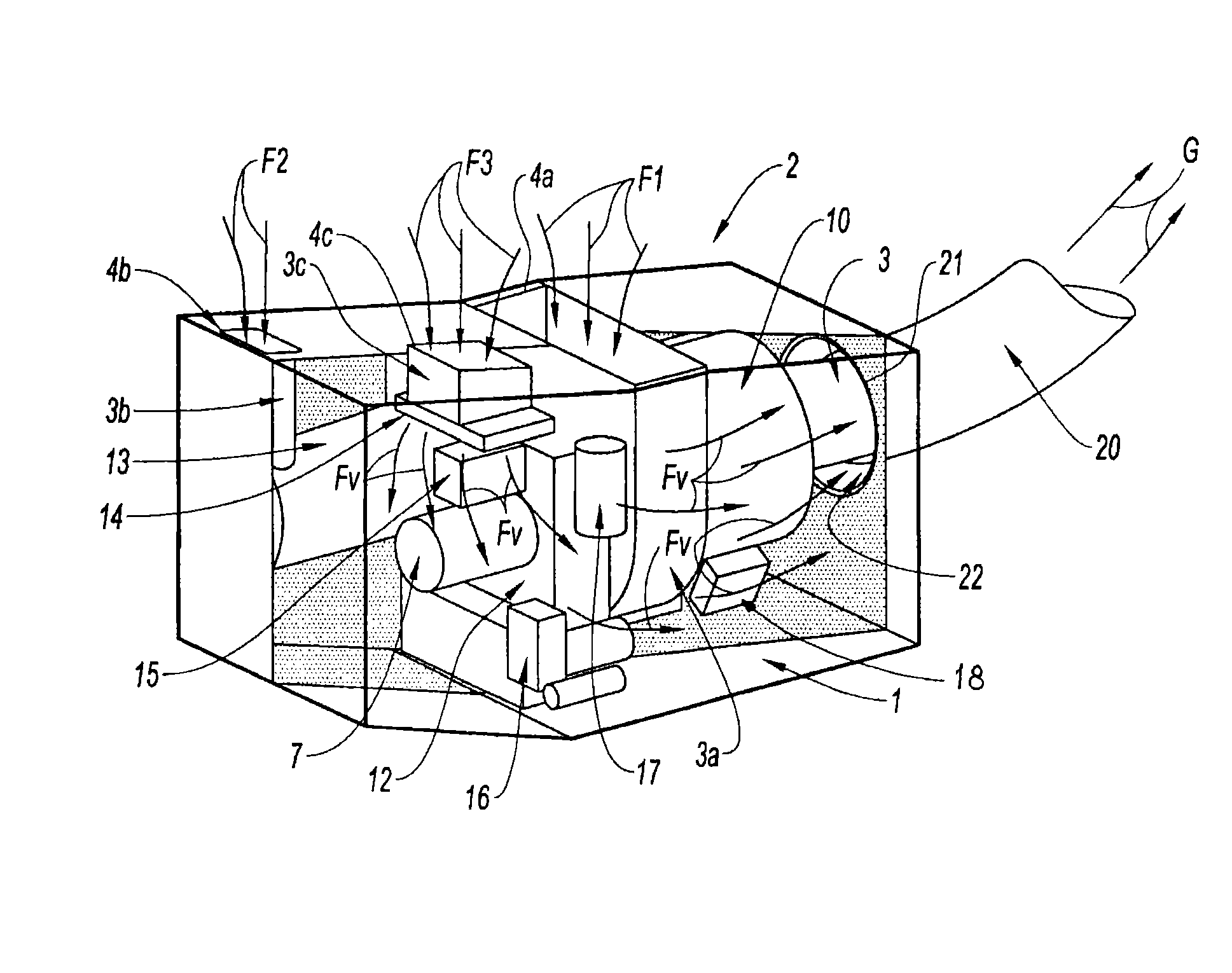
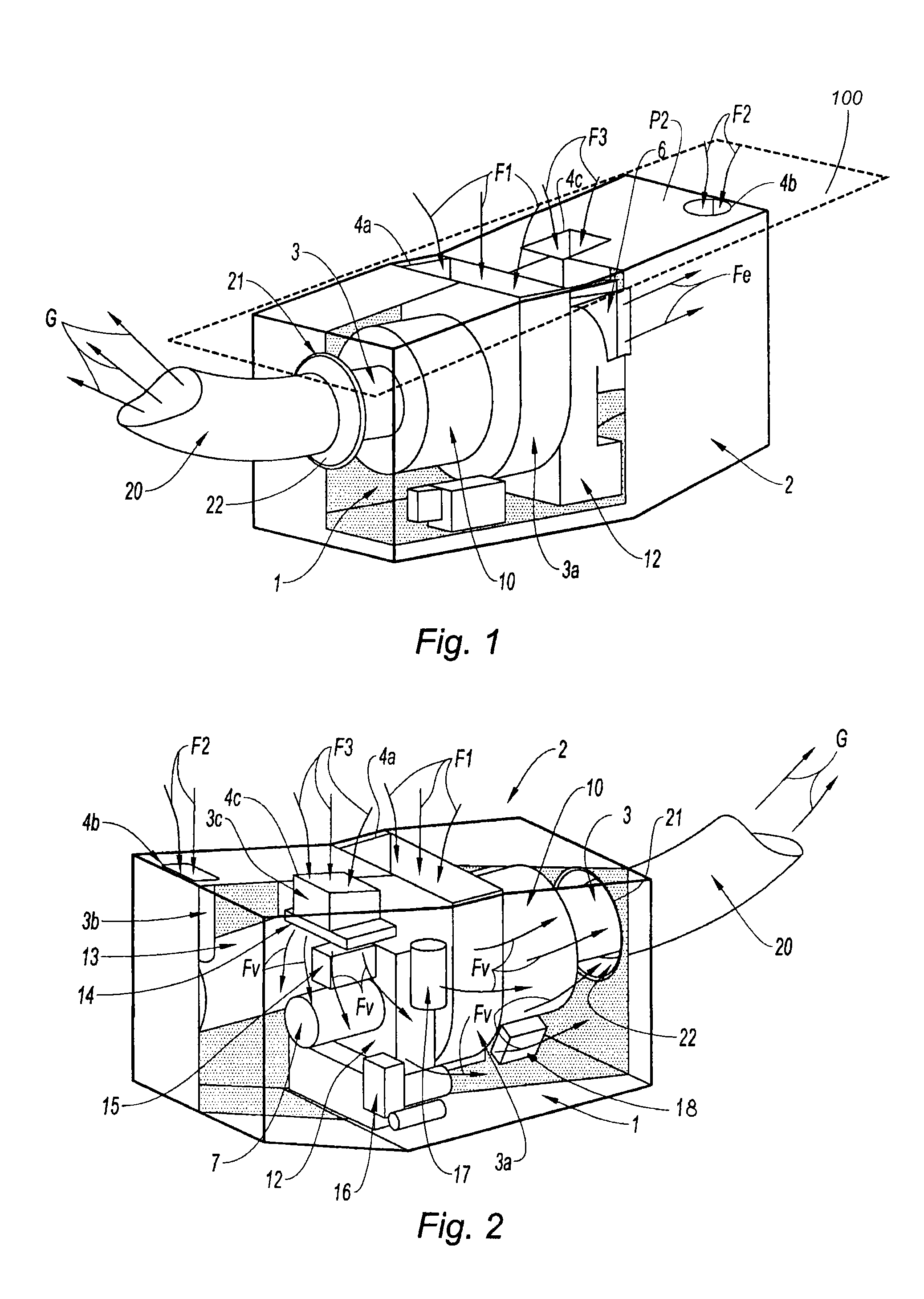
[0028]With reference to FIG. 1, the view in downstream-upstream perspective illustrates a plant 1 according to the invention in a closed compartment 2, partially cut away and arranged under the aircraft skin 100. This plant comprises an auxiliary power unit APU 10 and items of equipment mounted in connection with the APU. The compartment 2 is fitted with an exhaust nozzle 3 which leads into a gas discharger 20. This discharger 20 is mounted outside the compartment on an opening 21 formed in the compartment 2. In this figure, the gas discharger 20 appears in the foreground, coupled to the APU, itself coupled to an accessories box 12 capable of driving in particular an alternator 13 (see FIG. 2). The box 12 is a main transfer box incorporating pinions and reduction gears (not shown) with mu...


PUM


Abstract

A system and a method for ventilating a plant including an auxiliary power unit (APU) in an aircraft compartment are disclosed. The compartment is ventilated in an independent manner with individualized air feeds to each item of equipment concerned. According to one embodiment, a system for feeding and ventilating an aircraft auxiliary power source plant includes an APU and items of equipment mounted in connection with the APU. The APU is fitted with an exhaust nozzle which leads into a gas discharger mounted outside the compartment. Separate and independent ducts channel air between air inlets made through the compartment, and the APU and items of equipment. At least one ventilation duct that is separate and independent from the other ducts is coupled to an air inlet of the compartment in order to ventilate the APU and the items of equipment of the plant.

Description

TECHNICAL FIELD[0001]The invention relates to a method for feeding and ventilating with air an aircraft auxiliary power source plant centred on an auxiliary power unit (abbreviated as APU) or equivalent for supplying power on an aircraft. The invention also relates to an APU air feed and ventilation system capable of using such a method.[0002]An APU can supply power to the items of equipment (alternators, pumps, pressure compressors, air conditioning) of the aircraft, directly and / or indirectly via a power transfer box, abbreviated as BTP, with multiple outlets, notably during the transitional flight phases (take-off, acceleration, stationary flight for helicopters, etc.). During the stable phases, for example cruising, the main engines can generate the electricity necessary for the items of equipment via the APU running as a generator or via a standalone generator.[0003]The APUs are dedicated particularly to starting the main engines of the aircraft. For this purpose, the APUs supp...

Claims


Application Information

Patent Timeline
Patent Type & Authority Patents(United States)
IPC IPC(8): F02C6/00B64D41/00F02C7/32B64D33/02
CPCB64D41/00F02C7/32B64D2033/0213B64D2041/002
Inventor OUPLOMB, PATRICK
Owner SAFRAN POWER UNITS
Learn More