Mandrel conveying device for a tube rolling mill

a conveying device and tube technology, applied in forging presses, manufacturing tools, forging/pressing/hammering apparatuses, etc., can solve the problems of reducing the production efficiency of the rolling mill, affecting the quality of the dimensional quality, and the type of the rolling mill is subject to various drawbacks, so as to achieve more cost-effective production and high rolling process productivity.

Active Publication Date: 2015-12-08
DANIELI & C OFF MEC SPA
View PDF14 Cites 3 Cited by
  • Summary
  • Abstract
  • Description
  • Claims
  • Application Information

AI Technical Summary

Benefits of technology

[0020]It is a primary object of the present invention to make a mandrel conveying device for a tube rolling plant, with continuous multi-stand rolling mill operating with a mandrel, which is more cost-effective to make and to operate, guaranteeing a high productivity of the rolling process.
[0021]A further object of the invention is to make a mandrel conveying device for a tube rolling plant of the retained or semi-floating mandrel type which allows an accurate control of the mandrel speed during the rolling operations and which works in centred manner with respect to the traction exerted on the mandrel by the tube being rolled.

Problems solved by technology

On the other hand, this type of rolling mill is subject to various drawbacks.
The acceleration of the mandrel causes compression states in the tube which are detrimental to the dimensional quality and tubes faultiness because the groove delimited by the rolls is overfilled in the first stands and underfilled in the finishing stands at the end of the rolling mill.
Problems of rolling stability and of products with excessive tolerances are thus found.
Furthermore, the tube cooling is not uniform along the entire length of the tube because the head part of the tube where the mandrel no longer reaches, immediately after the first step of rolling, remains hot for a longer time, while the part behind, in which the mandrel is still inserted while rolling proceeds, is partially cooled by the mandrel itself with which it is in contact.
On the contrary, equivalent drawbacks to those of rolling mills of the previous type are found with regards to lack of temperature uniformity along the tube.
A limitation of this technology is thus its low productivity, in particular for rolling mills used for rolling small and medium sized tubes, e.g. those which have a nominal diameter smaller than or equal to 7″ (177.8 mm).
A disadvantage of the latter type of plant is that the process includes conveying the still very hot mandrel by means of pressing rolls with the risk of damaging the mandrel surface.
If the operating accuracy of the extractor device is not guaranteed there may be the risk of misalignment of the edges of two adjacent rolls with the consequent longitudinal marking of the rolled tube.
Indeed, in the case of rolling plant with semi-floating or retained mandrel, a retaining device with chain wrapped on sprockets and provided with hooking carriers is disadvantageous due to the premature wear of its components, the noise and the elongation that the chain undergoes over time.
In all cases, these systems do not work centred with the mandrel traction axis, and thus add problems related to flexion loads acting on the hooking / releasing systems.
In the known retained mandrel plants, described above, it is however difficult to make short tubes because the latter are shorter than the distance between the axis of the last stand of the multi-stand rolling mill and the first stand of the extractor.

Method used


Image

  • Mandrel conveying device for a tube rolling mill
  • Mandrel conveying device for a tube rolling mill
  • Mandrel conveying device for a tube rolling mill

Examples


Embodiment Construction

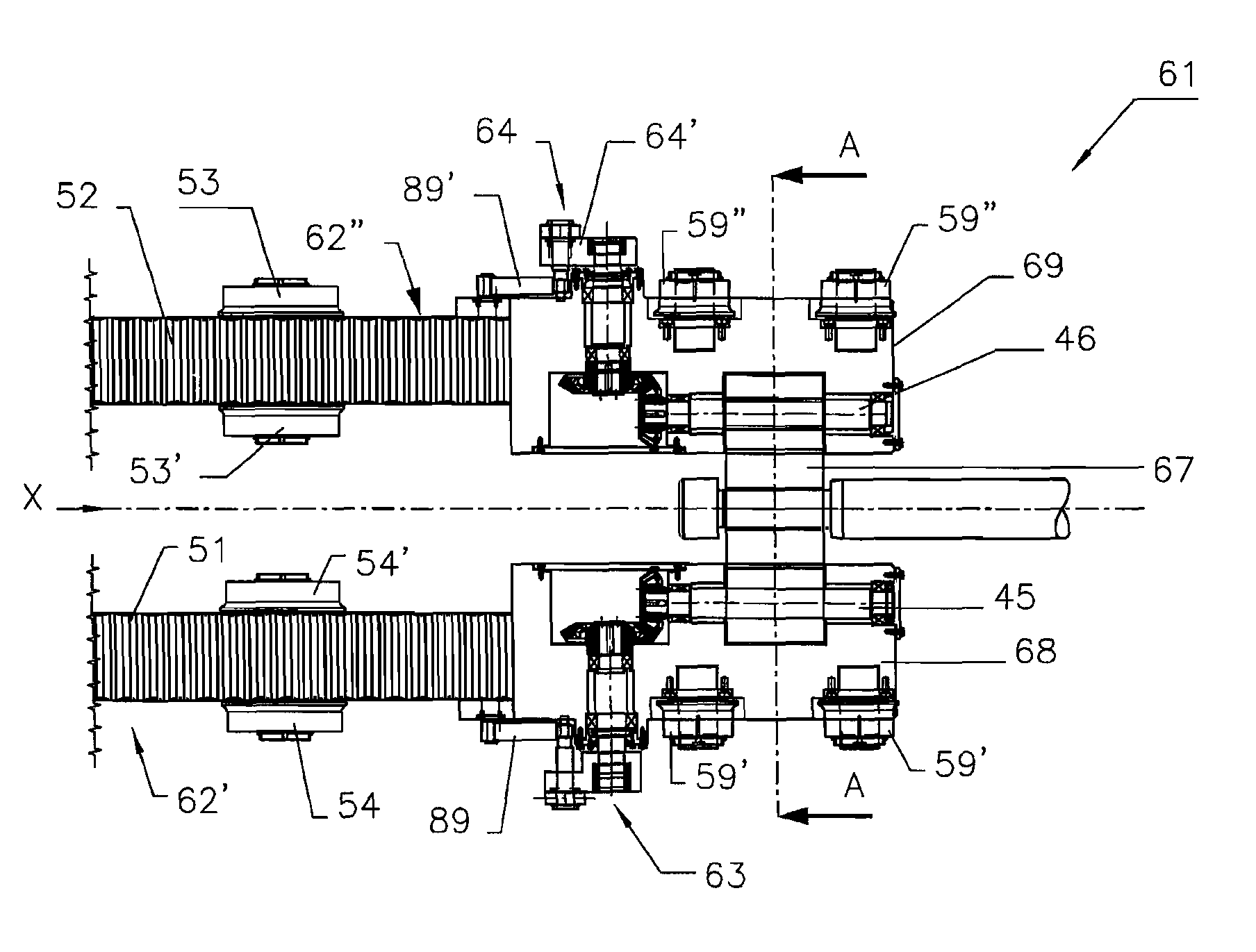
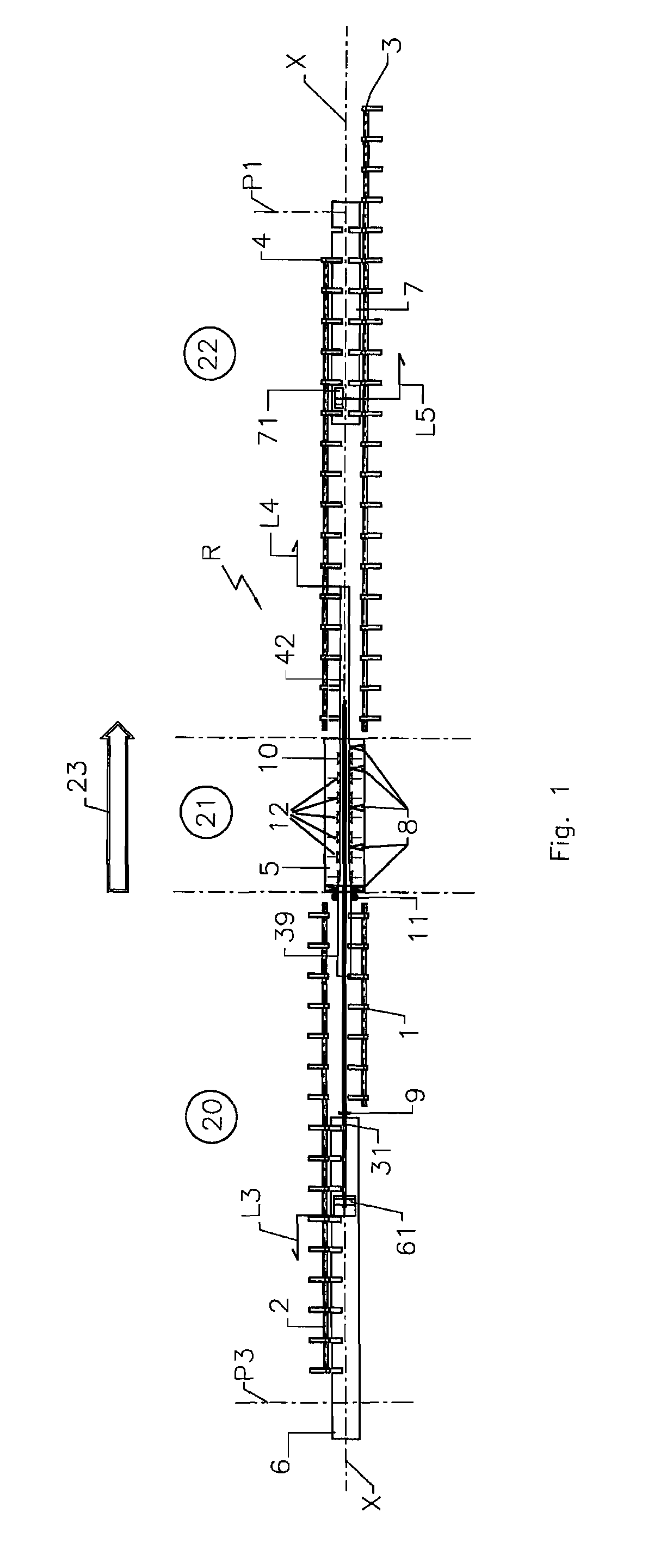
[0062]The figures show a preferred embodiment of a rolling plant, according to the invention, indicated globally by reference R, operating with a controlled speed mandrel, which may implement a continuous, controlled speed, high productivity mandrel tube rolling process comprising the conveying device of the invention. The rolling plant R defines a rolling axis X and a rolling direction 23 followed by the material to be rolled, commonly named pierced shell 39, and by the rolled tube 42. The plant R is conventionally split into an inlet area or side 20, in which the mandrel unloading device 2 for unloading the mandrel from rolling axis X and the pierced shell loading device 1 for loading the pierced shell on the rolling axis X are located, into a rolling area 21 proper, in which the multi-stand rolling mill 5 is located, and into an outlet area or side 22, in which the mandrel loading device 4 and the rolled tube unloading device 3 from the rolling axis X are located.
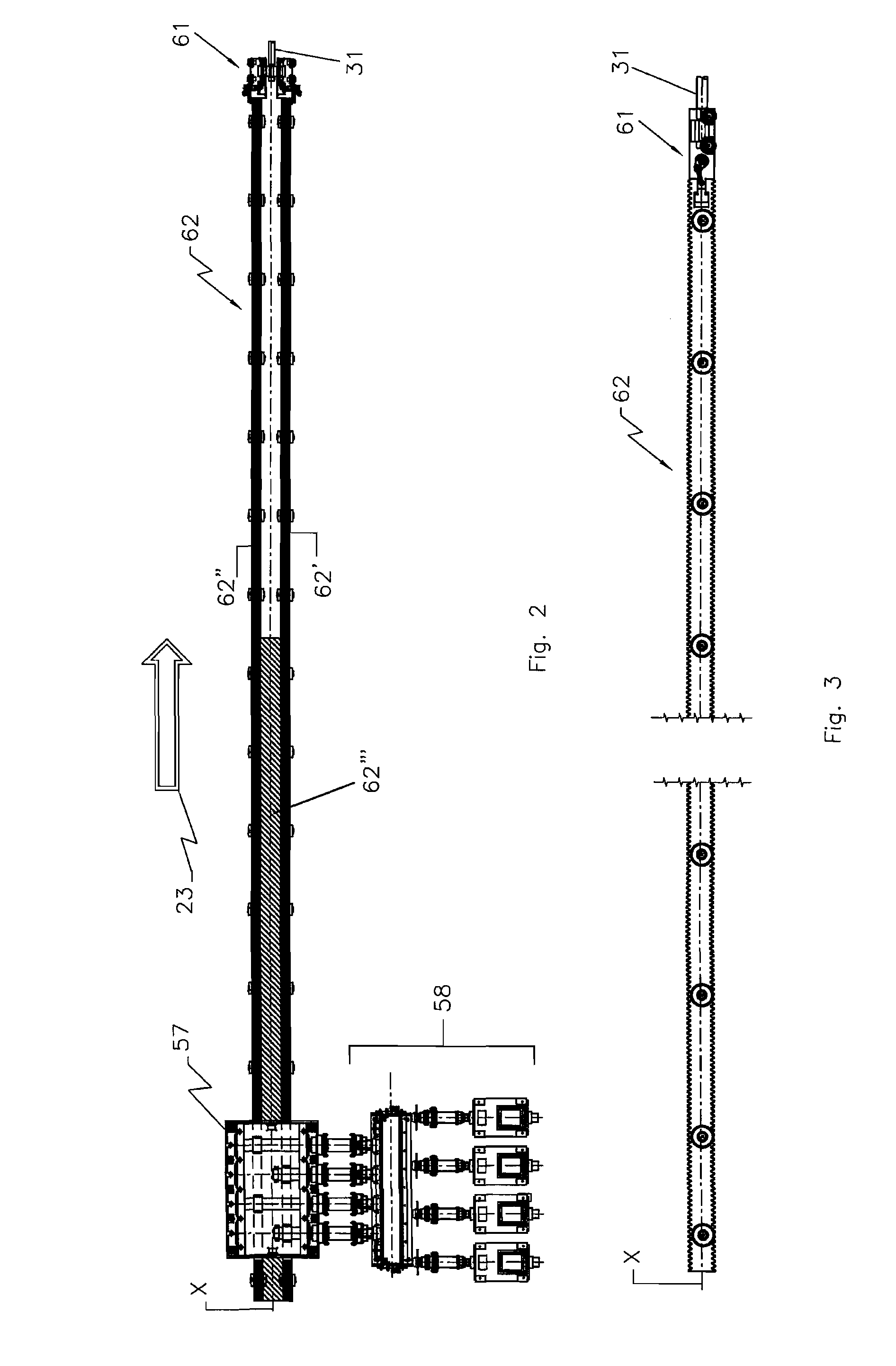
[0063]The loadin...


PUM

PropertyMeasurementUnit
lengthaaaaaaaaaa
lengthaaaaaaaaaa
speedaaaaaaaaaa

Abstract

A rolling plant (R) for rolling tubes having a multi-stand rolling mill (5) with two or more rolls, in order to implement a controlled speed mandrel rolling process, comprises a hooking and releasing device (61) which is arranged in the inlet area of the rolling mill (5) to cooperate with the rear tang of the mandrel (31) and a hooking and releasing device (71) which is arranged in the outlet area of the rolling mill (5) to cooperate with the front tang of the mandrel (31) in coordinated manner with the first hooking and releasing device (61).

Description

CROSS-REFERENCE TO RELATED APPLICATIONSSTATEMENT RE: FEDERALLY SPONSORED RESEARCH / DEVELOPMENTBACKGROUND[0001]1. Field of the Invention[0002]The present invention relates to a mandrel conveying device for a multi-stand continuous tube rolling mill operating with a mandrel.[0003]2. State of the Art[0004]Longitudinal multi-stand rolling mills of the prior art, operating with mandrel, may be grouped conventionally into various types, according to their architecture, with particular regards to the rolling speed control and to the speed and position of the mandrel within the tube.[0005]Continuous floating (i.e. free) mandrel rolling mills are those in which the mandrel can move freely inside the tube during the rolling passage through the multi-stand rolling mill according to the friction forces which are generated between mandrel and inner wall of the tube. The mandrel thus gradually accelerates as the rolling stands bite in sequence. The mandrel is removed from the tube at the end of th...

Claims


Application Information

Patent Timeline
Patent Type & Authority Patents(United States)
IPC IPC(8): B21B17/02B21C45/00B21B25/02B21B17/04
CPCB21B25/02B21B17/04B21C45/00B21B17/02
Inventor CERNUSCHI, ETTORESCALMANA, CLAUDIO MARIA
Owner DANIELI & C OFF MEC SPA
Why Eureka
Try Eureka