
Fire kindler

Active Publication Date: 2015-12-01
MAYFIELD ROBERT NICHOLAS
View PDF19 Cites 3 Cited by
  • Summary
  • Abstract
  • Description
  • Claims
  • Application Information

AI Technical Summary

Benefits of technology

The fire-kindler described in this patent is an easy-to-use and portable device made of a combustible material. It has a unique design that allows for a consistent and strong flame and is resistant to crosswinds. The device is packaged in a small, rigid tin and can be used both outdoors and indoors. It produces a hot spot on the firewood, which increases the speed of ignition and reduces heat dispersal. Overall, the fire-kindler provides a reliable and safe way to start a fire.

Problems solved by technology

Those familiar with any attempt to ignite a wood-fire are aware that adverse conditions may often exist to hinder the effort.
Wind and rain are common adverse conditions.
Vacationing campers will often employ rather bulky and heavy fire-kindlers.
Such kindlers are awkward to carry and therefore, not conducive for hiking situations.
If cut or broken so to reduce to portable size, they become less effective.
Then relying greatly upon the users' tedious and artful fire-building expertise.
a) Those with bulk, heaviness, and awkward shapes are not comfortably portable. Therefore, they are not conducive to hiking, biking, hunting and other active sports, including survival type outings.
b) Their bulkiness can be relative to their operation as well. Bulky shapes produce a dispersal of potential heat. The heat is distributed along the surfaces, resulting in numerous scattered flames. These flames often wrap around firewood, delivering even less than their potential.
c) For success, the dispersed heat delivery of these fire-kindlers relies upon various attempts to prolong the duration of self-consumption. The intention being, to last long enough to hopefully ignite a wood-fire.
d) In adverse conditions, kindlers with dispersed heat sources, and those with miniscule properties are easily extinguished. They can also be unsuccessful when the wind persistently blows their heat away, or, when the firewood becomes or remains wet.
e) Kindlers which have stick shapes often become smothered in part. They are inadvertently placed under, or between, stackings of the firewood. Also, they may quickly deteriorate during operation and collapse upon themselves. Thus, they can be wasteful and unsuccessful.
f) Waxy type kindlers allow for surprising messes in transport. Becoming soft, they become misshapen and even separate unintentionally. Then, whatever their shape they continue to deliver dispersed heat from numerous flames.
Often they fall apart during operation and subsequent disintergration.
Also, if comprised of moving parts they may malfunction.
j) Even when used indoors, wet wood may be encountered and the attempt may be unsuccessful.
Thus, increasing a rate of entropy and greatly increasing speeds of ignition.

Method used


Image

  • Fire kindler
  • Fire kindler

Examples


first embodiment

b>2 and 3

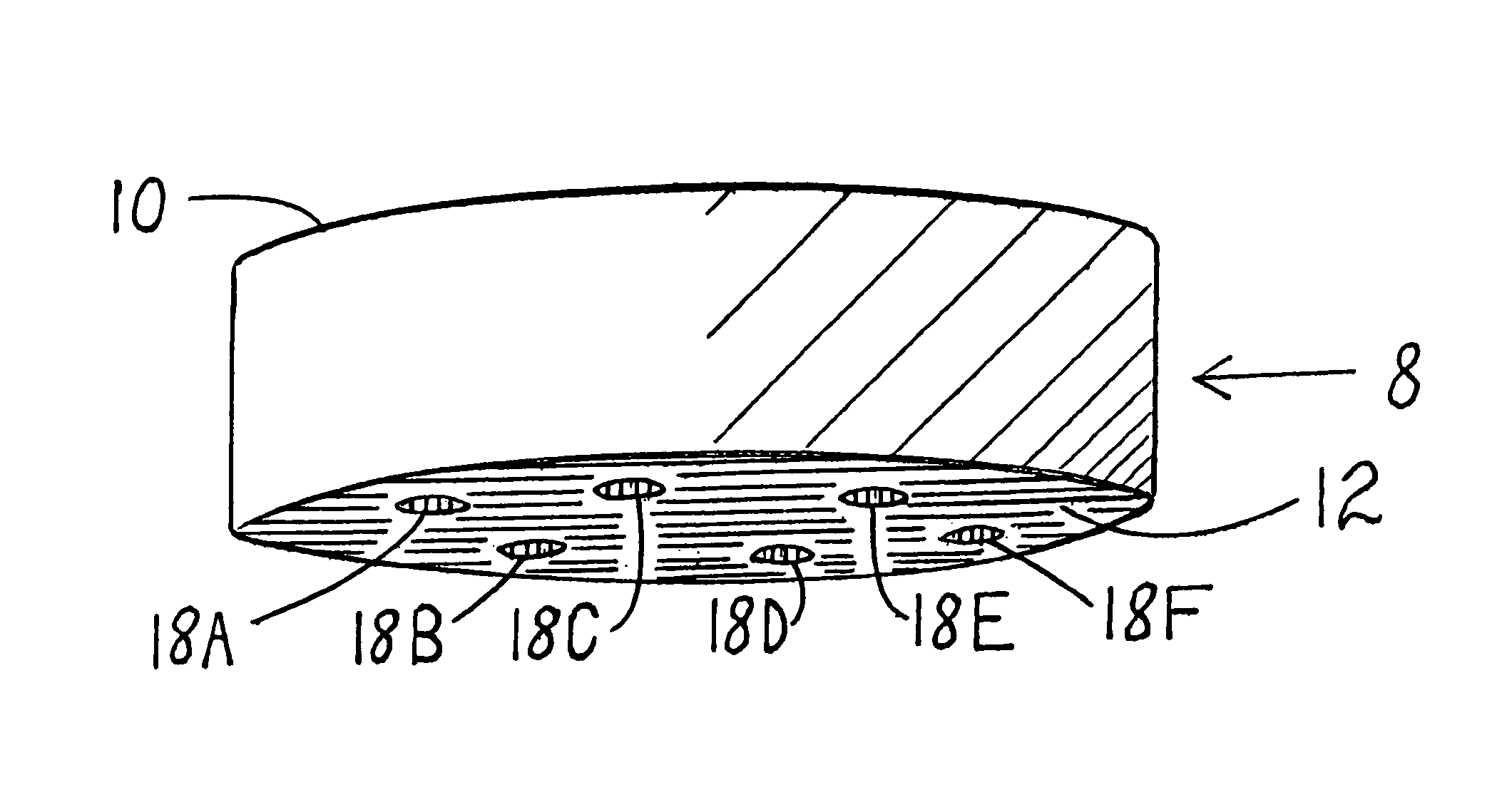
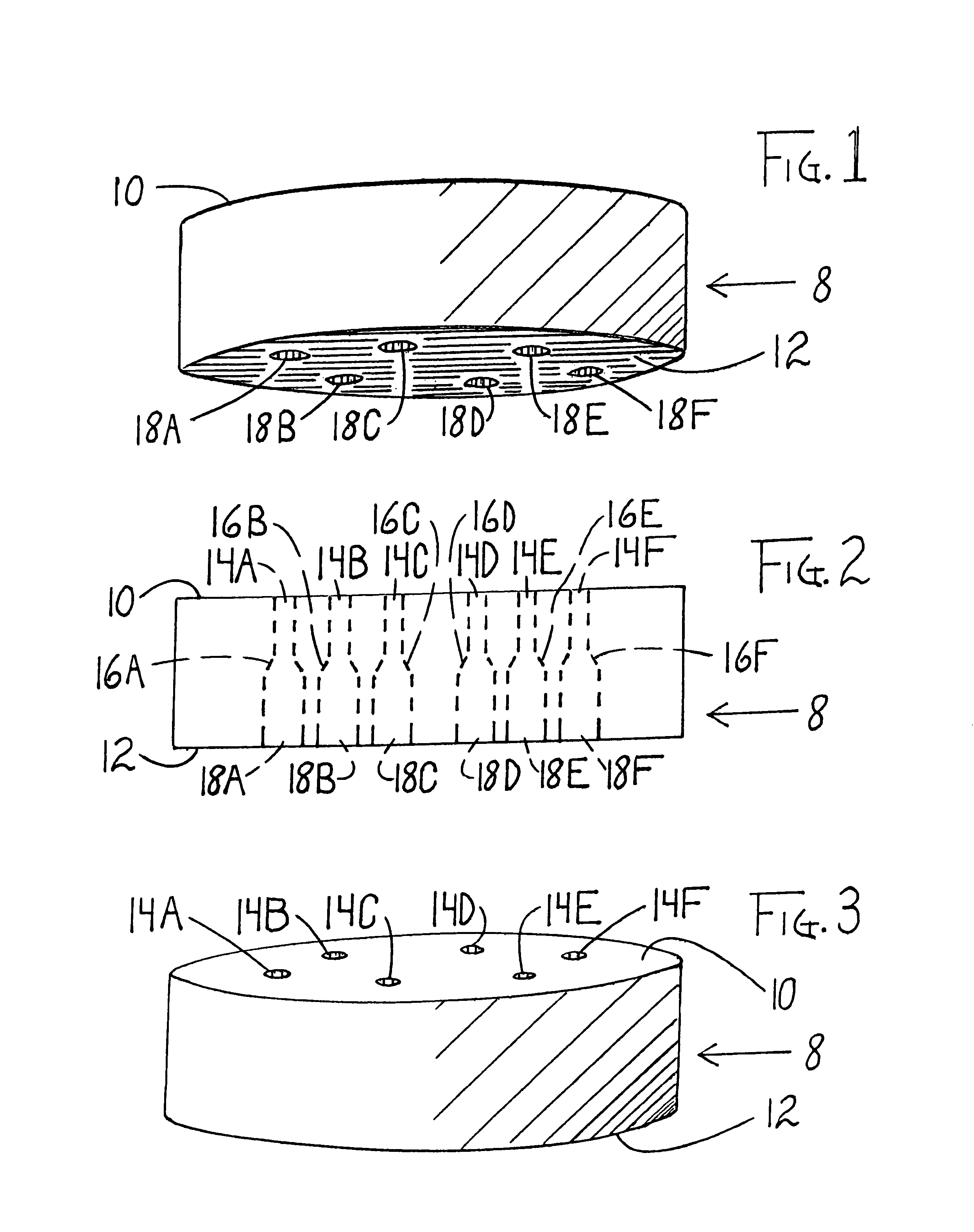
[0055]One embodiment of a fire-kindler is illustrated in FIG. 1, FIG. 2 and FIG. 3. Fire-kindler has a multiplicity of vertically rising air apertures which extend completely therethrough. An arrangement and plurality of which is shown, in one embodiment, at a sufficient plurality of six apertures.

[0056]Each aperture is an exact duplicate of each other aperture. A description of one aperture is exactly applicable to all apertures that exist in this one embodiment.

[0057]It is therefore described that the constituent parts of aperture 14A-16A-18A of FIG. 2 are mechanically introduced upon body of fire-kindler 8 of FIGS. 12 and 3 and are positioned sufficiently within its proportions. A boring tool with dimensions suitable to produce upper aperture 14A of FIGS. 2 and 3 is sent completely through body of fire-kindler 8 of FIGS. 1, 2 and 3. Having been introduced at an approximately perpendicular angle relative to top surface 10 of FIG. 2.

[0058]The boring tool is then removed an...


PUM


Abstract

One embodiment of a fire-kindler which produces a solitary flame cone comprised of pre-mixed air and fuel gases and an increased flame velocity. Comfortably portable in ones' back pocket, a conveniently accessible product of easy use. More reliable in and resistant to adverse outdoor conditions when igniting a woodfire. Comprised of a geometrically shaped plate of combustible material, body of fire-kindler 8 of FIGS. 1,2 and 3 has a multiplicity of air apertures 14A-16A18A, thru, 14F-16F-18F of FIG. 2 passing therethrough. Working co-operatively to produce a strong increased flame velocity in a more neutral solitary flame. Thus establishing a more intense heat output in a more persistently sturdy flame that remains more consistently focused among adverse winds. Thereby, increasing the application of heat and the speed and ease of firewood ignition.

Description

CROSS-REFERENCE TO RELATED APPLICATIONS[0001]This application claims the benefit of provisional patent application Ser. No. 61 / 571,258, filed 2011 Jun. 22 by the present inventor.BACKGROUNDPrior Art[0002]The following is a list of relevant prior art:U.S. PATENTSU.S. Pat. No. 18,287 September 1876 TyleeU.S. Pat. No. 201,184 March 1878 LewisU.S. Pat. No. 21,185 January 1879 BurnettU.S. Pat. No. 213,768 April 1879 McShaneU.S. Pat. No. 28,613 October 1883 Wood et. alU.S. Pat. No. 58,501 June 1897 McDonaldU.S. Pat. No. 82,972 August 1906 HillU.S. Pat. No. 2,007,694 July 1935 RutherfordU.S. Pat. No. 3,346,352 October 1967 McCoyU.S. Pat. No. 4,060,396(A) November 1977 BurtonU.S. Pat. No. 4,116,645 September 1978 DalzellU.S. Pat. No. 4,460,377 July 1984 KalilU.S. Pat. No. 4,781,128 November 1988 SalnerU.S. Pat. No. 4,952,217 August 1990 PorterU.S. Pat. No. 5,186,721 February 1993 CampanaU.S. Pat. No. 637,945 April 2002 ReigerForeign Patent DocumentsU.S. Pat. No. 402,838(A) December 1933 GBU...

Claims


Application Information

Patent Timeline
IPC IPC(8): C10L11/00A47J37/07F23Q13/00F24B15/00C10L11/02C10L11/04C10L11/06F23Q13/04C10L11/08C10L5/44F23Q13/02
CPCC10L11/02F24B15/005C10L11/06C10L11/04F23Q13/04C10L5/44F23Q13/02A47J37/0768F23Q13/00C10L11/08A47J37/079Y02E50/30Y02E50/10
Inventor MAYFIELD, ROBERT NICHOLAS
Owner MAYFIELD ROBERT NICHOLAS
Learn More