Dual energy imaging with beam blocking during energy transition

a dual-energy, beam-blocking technology, applied in the field of medical imaging, can solve the problems of reducing the transition time, and reducing the structure of the electronic circuit used in the scanner

Active Publication Date: 2015-12-01
GENERAL ELECTRIC CO
View PDF23 Cites 5 Cited by
  • Summary
  • Abstract
  • Description
  • Claims
  • Application Information

AI Technical Summary

Problems solved by technology

Efforts have already been made for limiting the transition time between the useful energies, but there remains a phase during which the patient receives an unnecessary dose.
Furthermore, reducing the transition time complicates the structure of the electronic circuit used in the scanner and makes the latter heavier.
However, with such a device, it is only possible to achieve dose modulation, but not to mask certain energies at given time intervals; the obtained result is therefore not satisfactory.

Method used


Image

  • Dual energy imaging with beam blocking during energy transition
  • Dual energy imaging with beam blocking during energy transition
  • Dual energy imaging with beam blocking during energy transition

Examples


Embodiment Construction

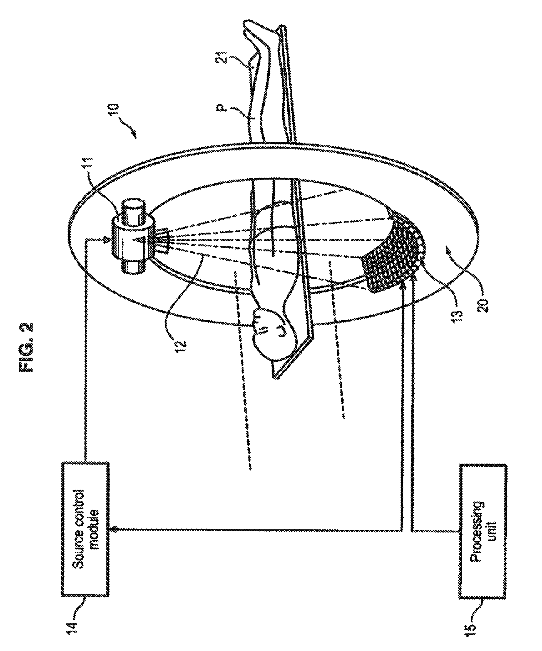
[0025]With reference to FIG. 2, a tomography device 10 comprising a source of radiations 11 and a detector of radiations 13, positioned on a rotating support 20 is illustrated. The source of radiations 11 emits a beam of radiations 12, for example X-rays, towards the detector 13 and through a patient P, or an area of a patient P to be imaged, lying on a support 21.

[0026]When the detector 13 receives the radiations 12, with a processing unit 15 connected to the detector 13, it is possible to store the images obtained by the detector 13 and optionally perform additional processing on these images, in order to, for example, reconstruct a 3D image of the area of the patient P to be imaged.

[0027]Further, the tomography device 10 comprises a module 14 for controlling the source 11, which is connected to the source 11 and in particular controls the dose and the energy of the radiations 12 emitted by the source 11 towards the patient P.

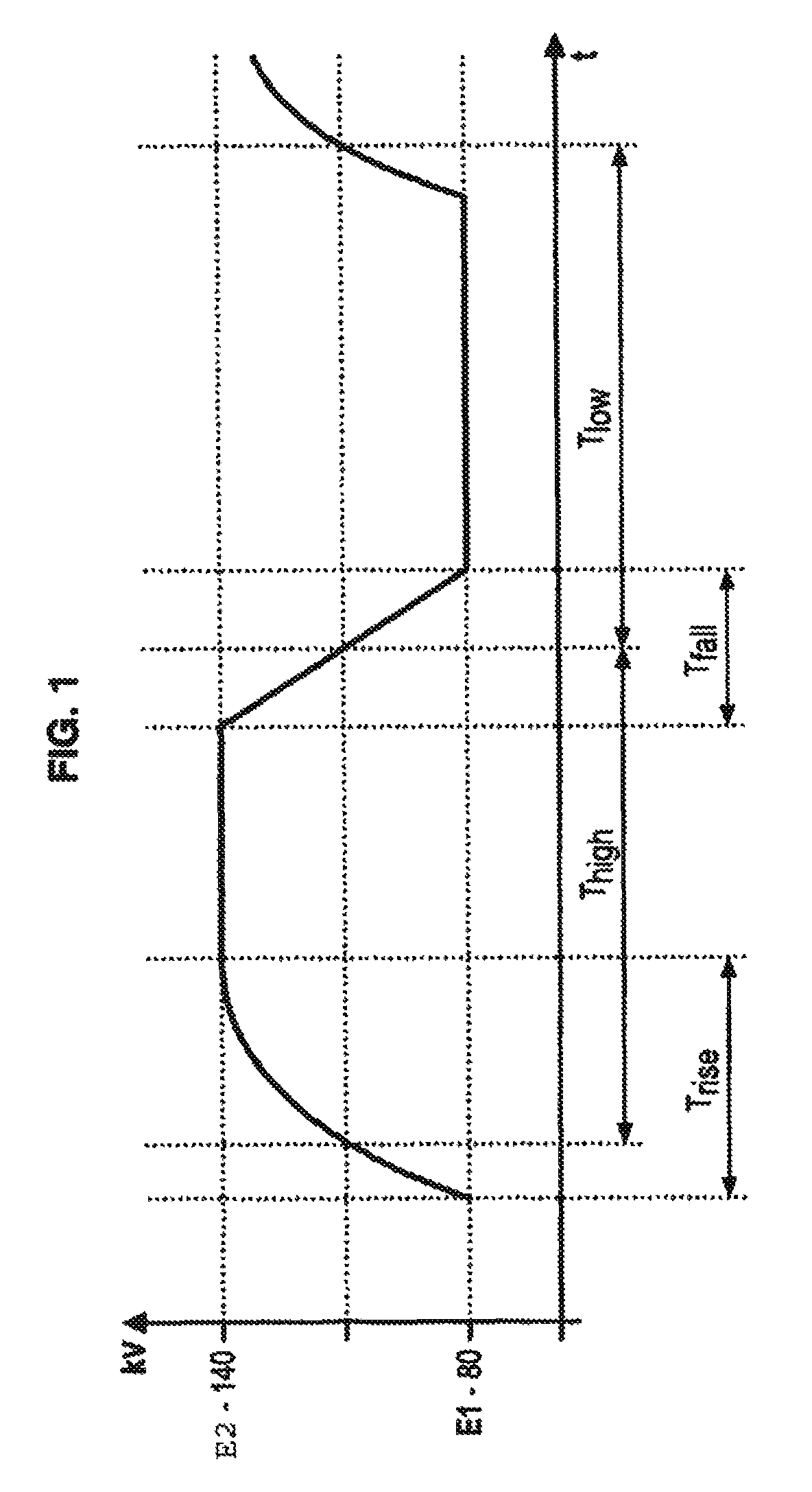
[0028]In the case of a dual-energy tomography device, t...


PUM


Abstract

A medical imaging method comprising generating a radiation at a first energy level by a radiation source, generating a radiation at a second energy level different from the first energy level by the radiation source, emitting the generated radiations at an output of the radiation source towards a detector, and blocking or diverting the emitted radiations during at least one intermediate phase during which the radiation source switches in a transient way from one of the first energy level and the second energy level to the other of the first energy level and the second energy level.

Description

BACKGROUND OF THE INVENTION[0001]1. Field of the Invention[0002]Embodiments of the present invention generally relate to the field of medical imaging and the field of radiography. More particularly, embodiments of the present invention relate to dual-energy scanners.[0003]2. Description of the Prior Art[0004]Dual-energy scanners may be single-source scanners periodically emitting radiations with two different energies typically of the order of 80 kV and 140 kV respectively, and switching very rapidly from one to the other (of the order of about a thousand switches per revolution of the scanner, and from about 0.5 to about 5 revolutions per second).[0005]As these radiations with different energies are not transmitted or reflected in the same way by organic tissues, notable enrichment of the information obtained in the final image, and an increase in its resolution may be achieved.[0006]As shown in the graph of FIG. 1, which represents the energies of the emitted radiations versus tim...

Claims


Application Information

Patent Timeline
Patent Type & Authority Patents(United States)
IPC IPC(8): H01J35/14H01J35/30G21K1/02H01J35/10A61B6/00
CPCA61B6/482A61B6/405A61B6/542G21K1/02H01J35/14H01J35/305H01J35/10H01J2235/166A61B6/4035H01J2235/086H01J35/153
Inventor WIEDMANN, UWEPERRILLAT-AMEDE, DENIS
Owner GENERAL ELECTRIC CO
Why Eureka
Try Eureka