
Method and device for performing diagnostics of an actuator, and actuator comprising one such device

a technology for actuators and diagnostics, which is applied in the direction of fault location by increasing destruction at fault, relays, instruments, etc., can solve the problems of not being able to determine whether the coiling of the actuator was short-circuited, and monitoring means that cannot be used on actuators controlled by electronics, etc., to achieve simple, economical, efficient

Active Publication Date: 2015-11-24
SCHNEIDER ELECTRIC IND SAS
View PDF21 Cites 0 Cited by
  • Summary
  • Abstract
  • Description
  • Claims
  • Application Information

AI Technical Summary

Benefits of technology

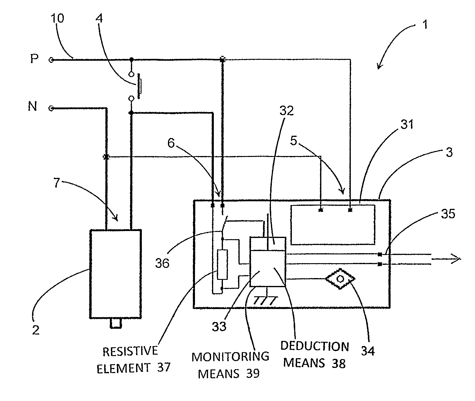
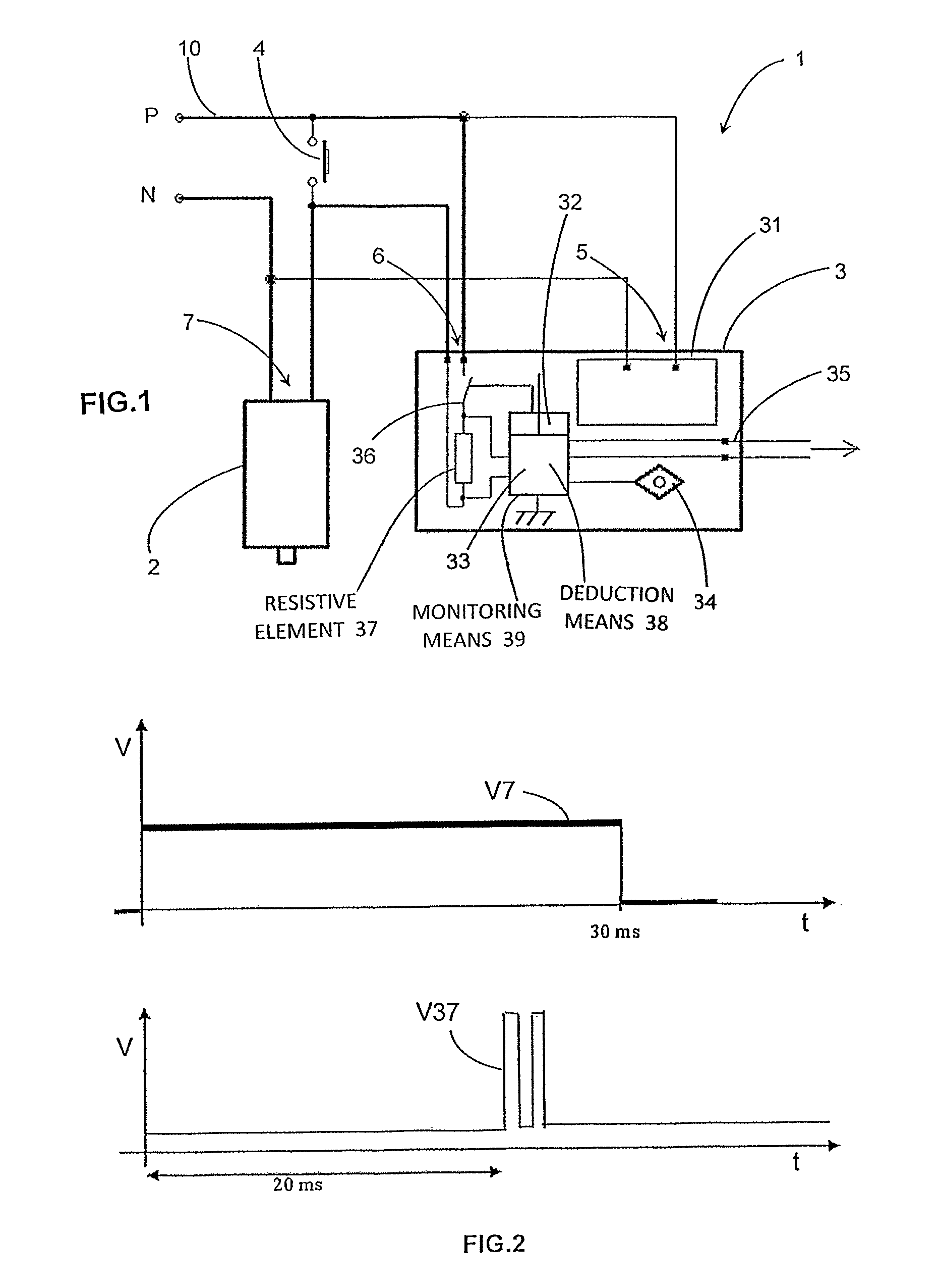
The invention provides a diagnostic method to solve problems with existing methods of diagnostics. The method is simple, cost-effective, efficient, and can check if the coil winding is not interrupted or short-circuited, and if the control electronics are not faulty.

Problems solved by technology

However, these means did not enable it to be determined whether the coiling of the actuator was short-circuited or not.
This monitoring means is not usable on actuators controlled by electronics—it does not give any information on the state of the actuator, but only gives information on its presence.

Method used


Image

  • Method and device for performing diagnostics of an actuator, and actuator comprising one such device
  • Method and device for performing diagnostics of an actuator, and actuator comprising one such device
  • Method and device for performing diagnostics of an actuator, and actuator comprising one such device

Examples


first embodiment

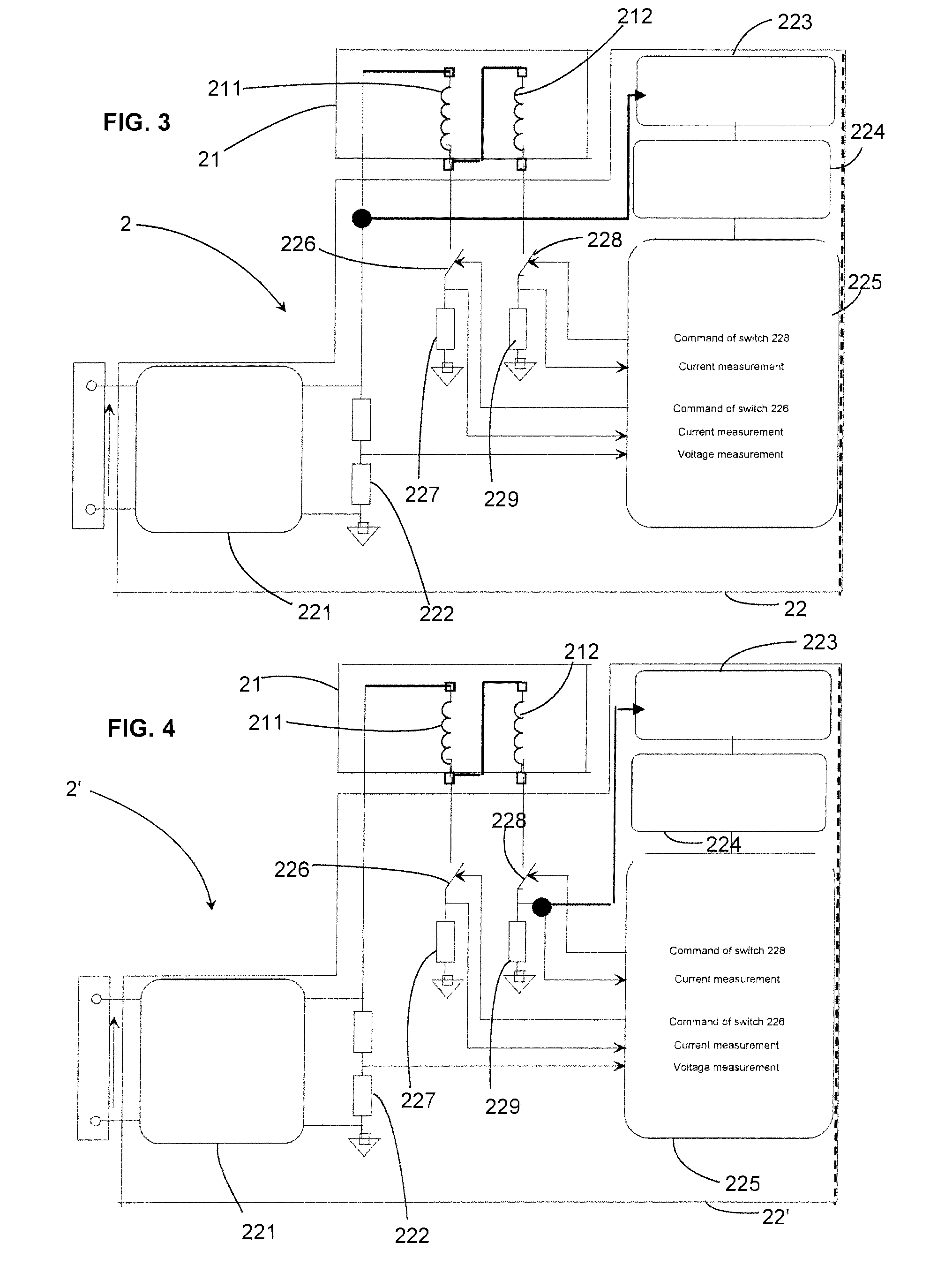
[0049]actuator 2 is described in the following with reference to FIG. 3. The actuator 2 mainly comprises a control device 22 and an electromagnet 21.

[0050]The electromagnet comprises for example a first inrush coil 211 and a second holding coil 212. The coils are for example connected in series.

[0051]The control device mainly comprises a converter 221 for converting the electric power supply signal of the actuator into an electric signal suitable for supply of the electromagnet, a logic processing unit 225 such as a microcontroller, a power supply 223 and a voltage regulator 224 to supply power to this logic processing unit, control means 225, 226 of the power supply of the first coil, control means 225, 228 of the power supply of the serially connected set of first and second coils, means 225, 227 for determining an intensity of the current flowing in the first coil, means 225, 229 for determining an intensity of the current flowing in the serially connected set of first and second...

second embodiment

[0060]A detail of embodiment of the control device is described in the following with reference to FIG. 5.

[0061]In this embodiment, a controlled switch 303 is connected in series with the holding coil 212 and a Zener diode 307 between the terminals of the converter 221. A series connection of a diode 308 and capacitor 309 is further connected in parallel to the Zener diode. A series connection of the controlled switch 228 and measuring resistor 229 is also connected in parallel to the Zener diode. The controlled switch 303 is connected to the logic processing unit 225 and to an output terminal of the converter 221 via a pull-up resistor 302. In this way, as soon as the converter 221 supplies a voltage, the controlled switch 303 is closed. A diode 304 is connected in parallel to the holding coil.

[0062]The controlled switch 228 is further controlled by the logic processing unit 225 and therefore enables the Zener diode to be short-circuited to measure the current flowing in the holdi...


PUM


Abstract

A diagnostic method for an actuator having a coil and a control device for supplying power to the coil, by controlling a power supply to the actuator by a diagnostic device, controlling a supply of power to the coil by a control device, monitoring an electric signal supplying the actuator, and deriving a diagnostic indicator of the actuator from a result of monitoring; and a device and computer code for executing the method.

Description

BACKGROUND OF THE INVENTION[0001]The present invention relates to a method for performing diagnostic of an actuator comprising a coil and a control device of power supply of the coil, in particular an electric circuit breaker actuator. It also relates to a device for performing diagnostic of the power supply of a coil of an actuator enabling the diagnostic method to be implemented. It also relates to an actuator comprising a coil and at least one such diagnostic device. It finally relates to a computer program comprising computer program code means suitable for execution of steps of the diagnostic method.STATE OF THE ART[0002]Actuators designed to command opening and closing of circuit breakers are known and are nowadays formed by integrated control electronics and associated with an electromagnet coil. The role of these electronics has enabled functionalities to be added which have mainly enabled the volume of the actuator to be reduced.[0003]These actuators were beforehand only fo...

Claims


Application Information

Patent Timeline
Patent Type & Authority Patents(United States)
IPC IPC(8): G01R31/02H01H11/00H01H47/00H01H47/06
CPCH01H11/0062H01H47/002H01H47/06H01H2300/052
Inventor CHELLOUG, MUSTAPHA
Owner SCHNEIDER ELECTRIC IND SAS
Learn More