
Rolling bearing device, in particular for a steering column

a technology of rolling bearings and steering columns, which is applied in the direction of elastic bearings, rigid support of bearings, transportation and packaging, etc., can solve the problems of large number of parts which must be manufactured and assembled, and the device is not sufficiently compact in the axial dimension, so as to achieve the effect of convenient manufacture and mounting

Active Publication Date: 2015-11-24
AB SKF
View PDF10 Cites 1 Cited by
  • Summary
  • Abstract
  • Description
  • Claims
  • Application Information

AI Technical Summary

Benefits of technology

The present invention is about a new type of bearing that is easy to make and install. It is small and has very few parts. This makes it efficient and compact in its design.

Problems solved by technology

Such a rolling bearing device has the major drawback of comprising a large number of parts which must be manufactured and assembled.
Moreover, such a device is not sufficiently compact in the axial dimension.

Method used


Image

  • Rolling bearing device, in particular for a steering column
  • Rolling bearing device, in particular for a steering column
  • Rolling bearing device, in particular for a steering column

Examples


Embodiment Construction

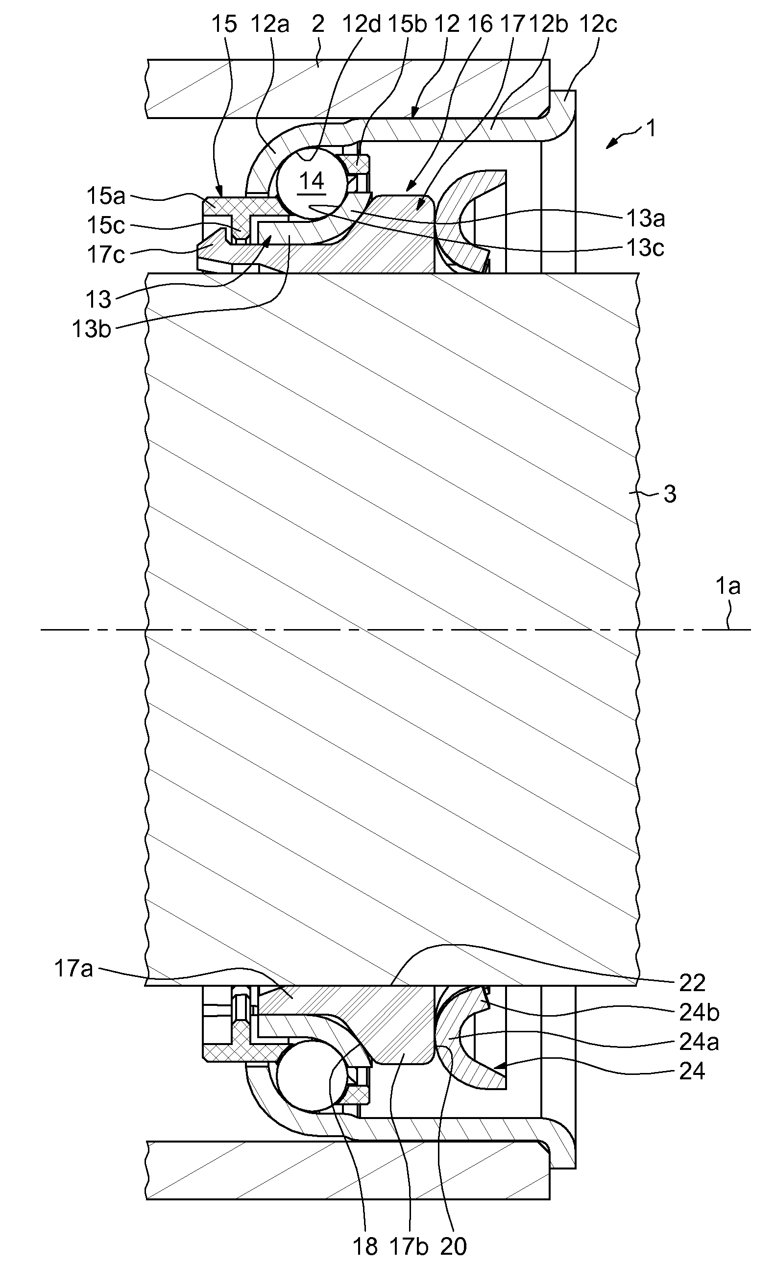
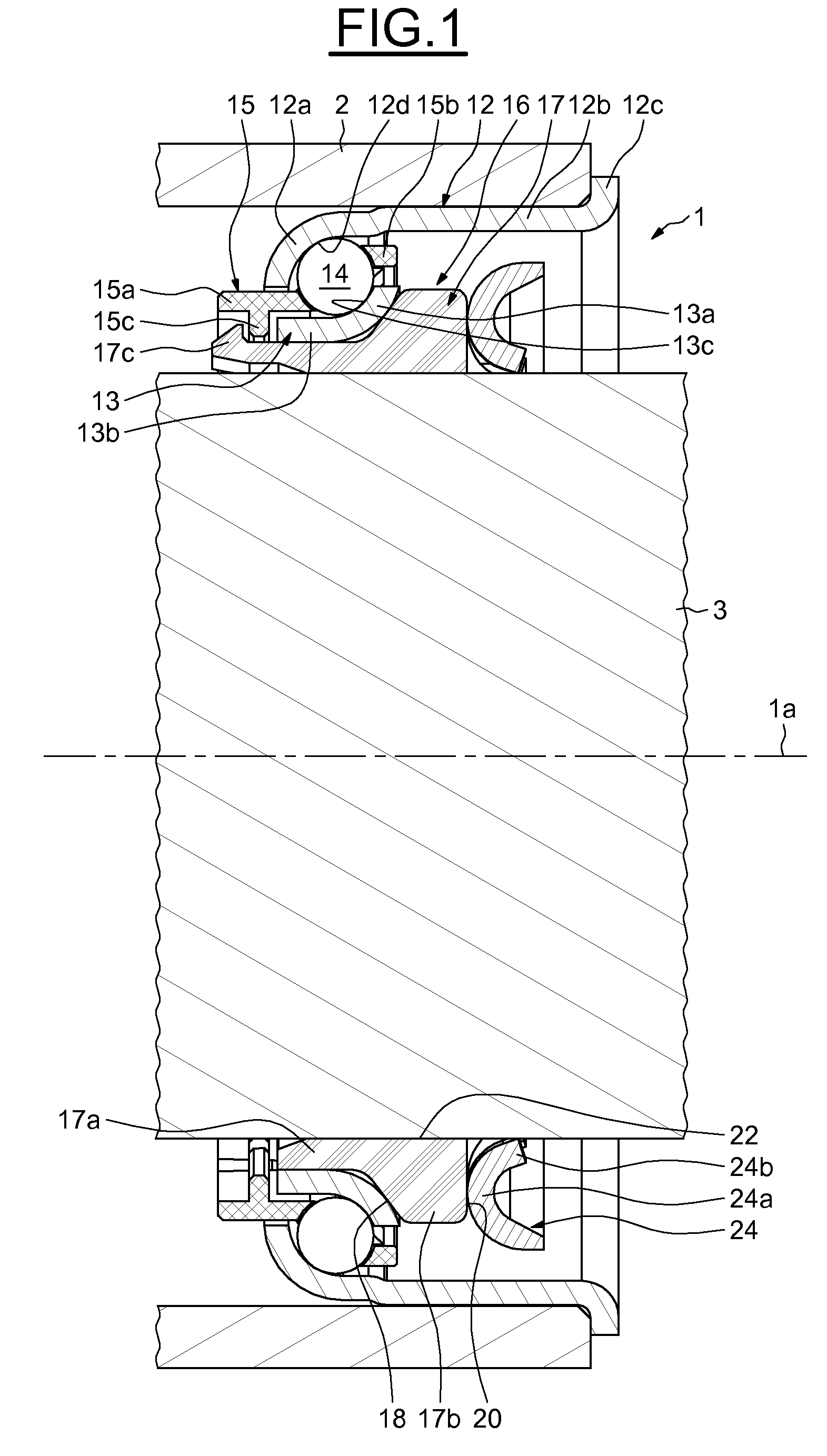
[0023]In FIG. 1, the rolling bearing device, referenced 1 in its entirety, of axis 1a, is designed to be mounted in a motor vehicle steering column between a tubular housing 2 comprising a bore and a rotating shaft 3 which is coaxial with the housing 2 and is mounted in the housing.

[0024]The rolling bearing device 1 comprises an outer ring 12, an inner ring 13, a row of rolling elements 14, such as for example balls, arranged between the rings, a cage 15 for maintaining the regular circumferential spacing of the rolling elements 14 and a tolerance ring or sleeve 16 mounted in the bore of the inner ring 13. The inner ring 13 is mounted in direct axial contact with the sleeve 16.

[0025]The outer ring 12, made in one piece, comprises a toroidal portion 12a, a cylindrical axial portion 12b and a radial rim 12c. The axial portion 12b is arranged axially between the toroidal portion 12a and the rim 12c, and comes into radial contact against the bore of the tubular housing 2. The toroidal p...


PUM

PropertyMeasurementUnit
elasticaaaaaaaaaa
forceaaaaaaaaaa
elastic deformationaaaaaaaaaa

Abstract

A rolling bearing device for a steering column includes an outer ring, an inner ring, at least one row of rolling elements arranged between the rings, and a sleeve mounted in the bore of the inner ring and coming to bear axially against the ring. The sleeve provides a bore designed to come into radial contact with a shaft, and a member for the axial retention of the sleeve that is designed to engage with the shaft. The sleeve has at least one elastic body at least partially delimiting the bore. The axial retention member is mounted to bear axially directly against the sleeve on the opposite side from the inner ring.

Description

CROSS-REFERENCE TO RELATED APPLICATIONS[0001]This Application claims priority to French Patent Application FR1356660 filed Jul. 5, 2013, the contents of which are herein fully incorporated by reference.FIELD OF THE INVENTION[0002]The present invention relates to the field of rolling bearing devices, notably rolling bearings used in motor vehicle steering columns.BACKGROUND OF THE INVENTION[0003]Steering columns generally comprise a shaft, one end of which is secured to a steering wheel that drives it and is turned by the driver of the vehicle and the other end of which is secured to mechanical members the role of which is to perform the angular positioning of the wheels of the vehicle. The steering column shaft is mounted such that it can rotate in a tubular housing via two rolling bearing devices each comprising a rolling bearing, generally an angular-contact ball bearing, which are mounted in opposition.[0004]The rolling bearing generally comprises an inner ring and an outer ring,...

Claims


Application Information

Patent Timeline
Patent Type & Authority Patents(United States)
IPC IPC(8): F16C27/06F16C19/06B62D1/16B62D65/00F16C25/08F16C35/073F16C19/16
CPCF16C27/066B62D1/16B62D65/00F16C19/06F16C25/083F16C35/073F16C19/163F16C2326/24Y10T29/49696
Inventor BUSSIT, SYLVAINJANSEN, DANIELJULLIEN, TOMMYLEPINE, THOMASMONTBOEUF, BRUNO
Owner AB SKF
Learn More