High-pressure chamber

Active Publication Date: 2015-11-24
BOEHRINGER INGELHEIM INT GMBH
View PDF19 Cites 18 Cited by
  • Summary
  • Abstract
  • Description
  • Claims
  • Application Information

AI Technical Summary

Benefits of technology

The present invention relates to a method of manufacturing components for high pressure applications using metal injection molding (MIM) technology. The invention provides a way to join components together by creating connecting elements, such as arms or zig-zag rings, which are deformed or bent when the components are locked together. This joining method, called crimping, allows for faster assembly and improved positional tolerances compared to screw connections. The use of MIM technology also allows for the production of components with improved corrosion resistance and compatibility with active substances. Additionally, the invention includes a method of coating the components with plastics to achieve elastic sealing and pharmaceutical compatibility. The invention also mentions the advantages of lining the interior of a sintered metal component with plastics to seal open pores and smooth the surface, reducing the dead volume in the system and improving the start-up phase of the system.

Problems solved by technology

High pressure pumping systems, on the other hand, are generally known from various industrial applications but are not really suitable for use in technical medical equipment as they are often made of materials that are not compatible with the particular medical active substances or may even release substances that are toxic to the patients.
Moreover, industrial pumping systems are often of a mechanically complex nature so that it is difficult to reduce them to the size of handheld medical equipment, in particular.
In order to achieve this using nozzle pump arrangements without the use of propellants, pressures of 100-1200 bar are required in the associated pump chambers, with high demands on the leak-tight construction of the system.
Often, they cannot be made of the comparatively cheap plastics that are otherwise conventional for mass produced components in medical technology.
The sealing requirements for a pulsed system of this kind have not only static but also dynamic aspects compared with continuous pumping, which means that the connecting technology, particularly between the high pressure chamber and the outlet nozzle, is subject to particular demands.

Method used


Image

  • High-pressure chamber
  • High-pressure chamber
  • High-pressure chamber

Examples


Embodiment Construction

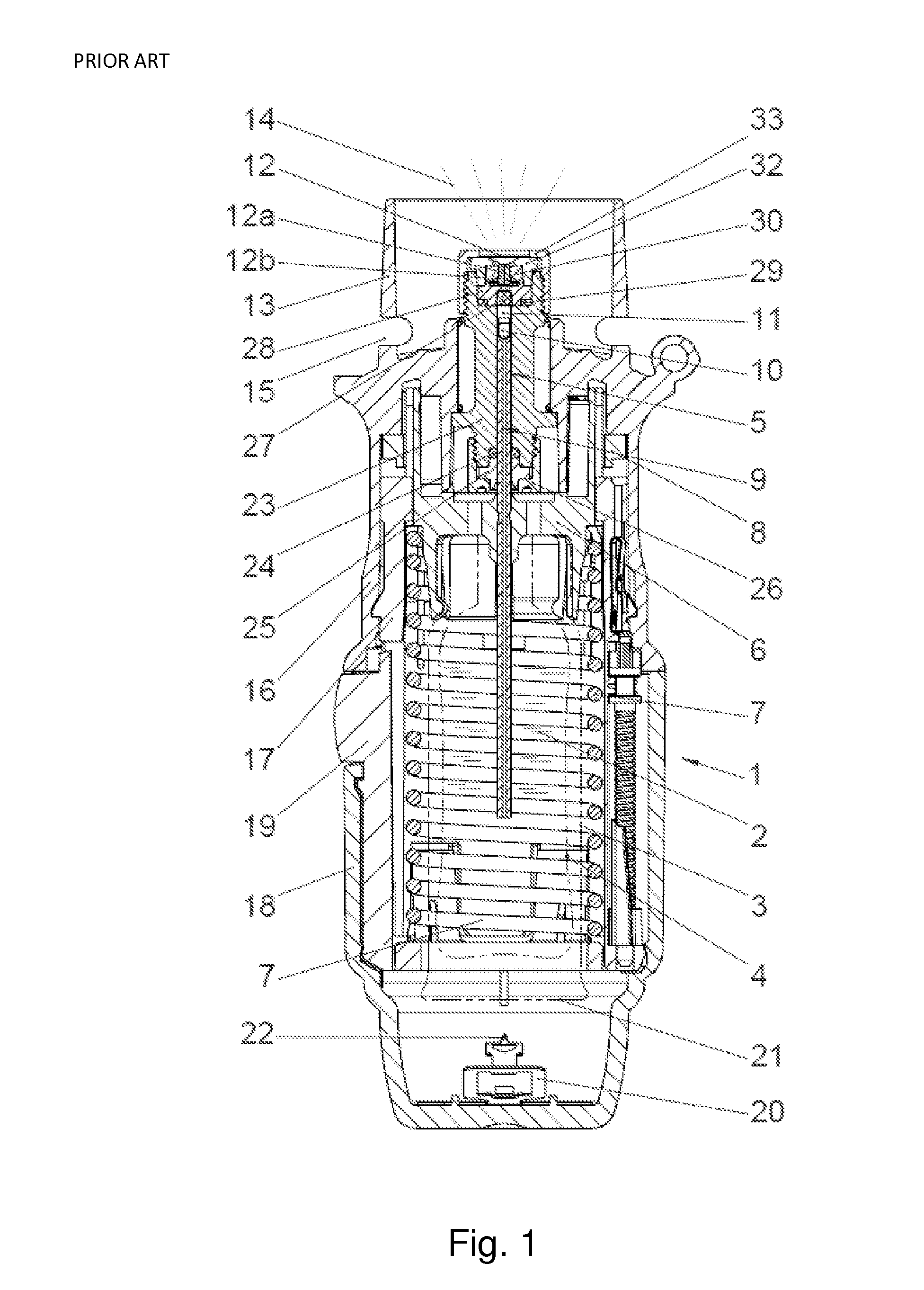
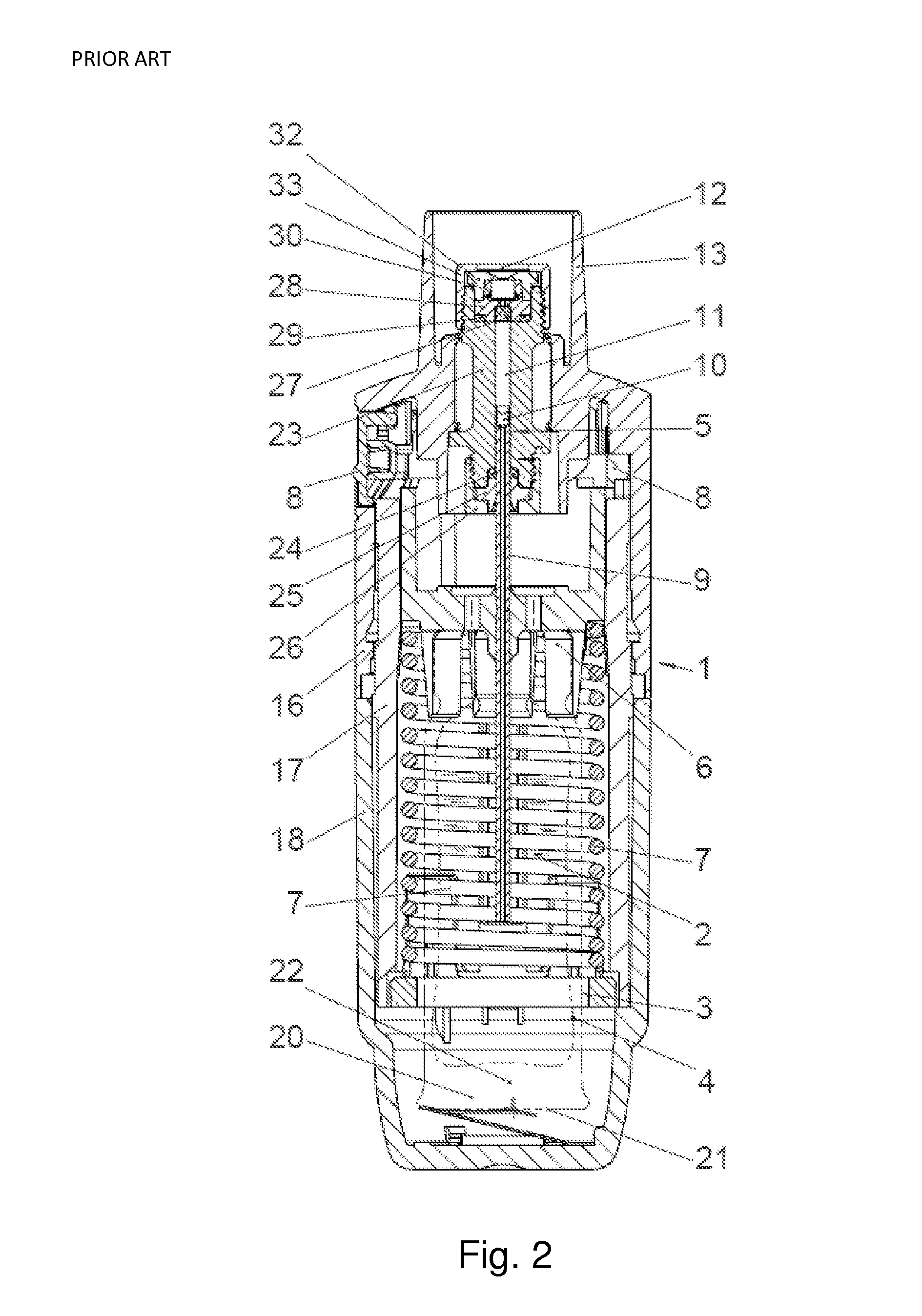
[0030]FIGS. 1 and 2 show in a schematic representation a known manually operated nebuliser (1) for nebulising a liquid (2), in which the pressure chamber (11) can be replaced by the proposed high pressure chamber. The nebuliser from FIG. 1 and (2) is a metering nebuliser which dispenses a given dose of liquid on each actuation cycle. During operation of the nebuliser a distinction is made between the untensioned state in which the metering volume in the pressure chamber (11) is unfilled (FIG. 1) and the tensioned state in which the pressure chamber (11) is filled (FIG. 2). The pressure chamber (11) corresponds in its function to a pumping chamber.

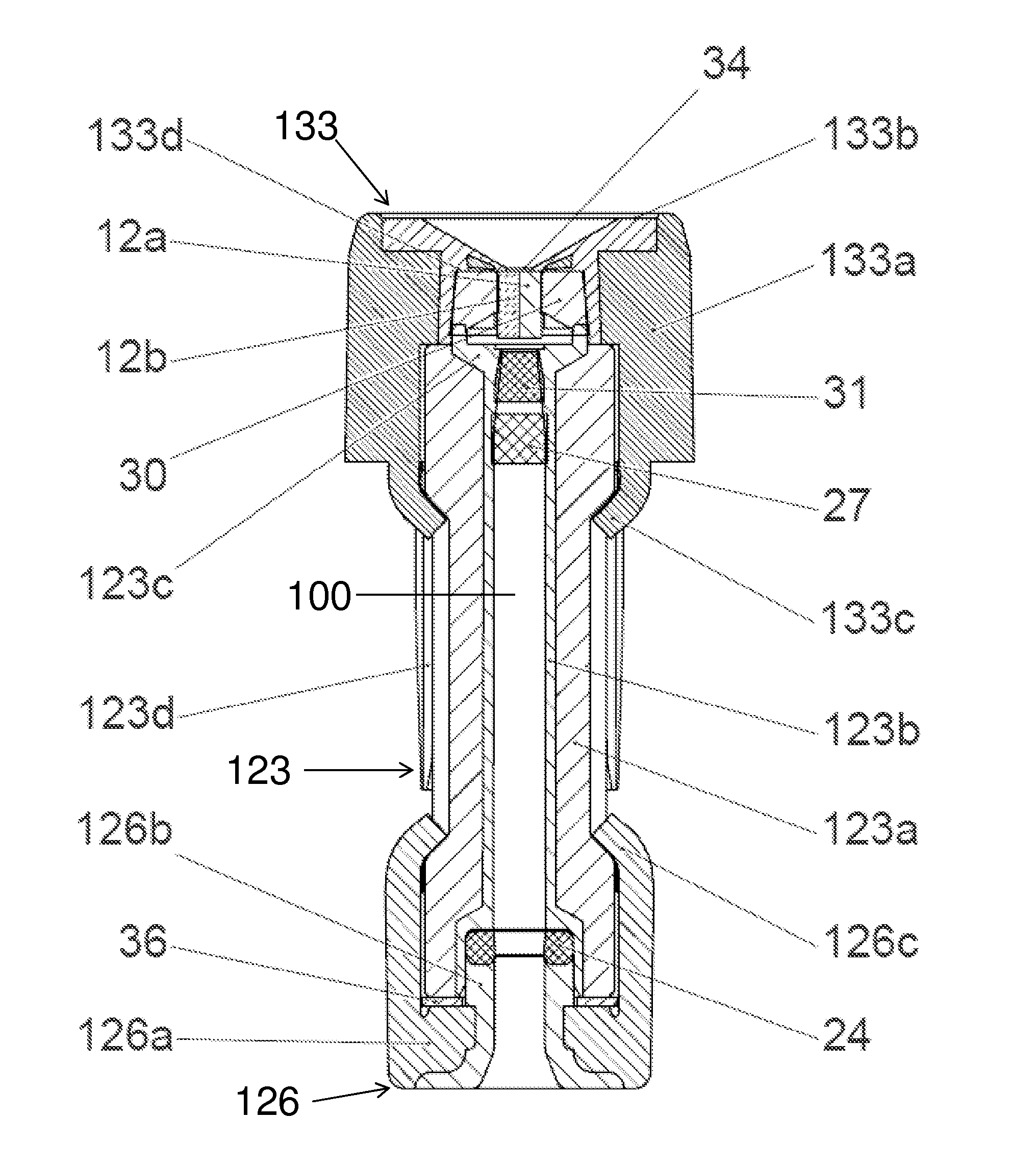
[0031]The strength-determining components of this pressure chamber are a central part (23) which is substantially cylindrical in its interior, for example made of a solid plastic such as, preferably, PEEK, a support ring (25) screwed to this central part (23) in the upstream direction by a first check nut (26) and a nozzle holder (32) screw...


PUM

PropertyMeasurementUnit
Pressureaaaaaaaaaa
Pressureaaaaaaaaaa
Lengthaaaaaaaaaa

Abstract

The invention relates to a high-pressure chamber for preferably atomizing or injecting metered amounts of fluid, such as pharmaceutical preparations. The components of the high-pressure chamber determining the strength thereof are made of a sintered metal body having plastic regions directly attached thereto. The plastic regions allow corrosion resistance and material compatibility of the interior of the high-pressure chamber and fluids placed under pressure therein. The shape of the sintered metal body provides the entire system with the rigidity required for high-pressure operation and with directly molded connection elements prescribing the type of connection to other components. The components of the high-pressure chamber determining the strength thereof are thereby deformed or crimped to each other, so that inexpensive and quick overall assembly processes are available.

Description

FIELD OF THE INVENTION[0001]The present invention relates to a high pressure chamber which is made up of a plurality of individual parts and is operated by liquid.BACKGROUND OF THE INVENTION[0002]It is known that in most medical procedures in which liquids are administered to a patient's body or are conveyed inside technical medical equipment, very low pressures are used, for example when setting up infusions or in medical procedures in which blood or other physiological liquids are circulated. Conventional dispensing systems for cosmetics or medical pressurised gas atomisers also generally operate at below 7 bar of liquid pressure, very rarely up to 20 bar. High pressure pumping systems, on the other hand, are generally known from various industrial applications but are not really suitable for use in technical medical equipment as they are often made of materials that are not compatible with the particular medical active substances or may even release substances that are toxic to t...

Claims


Application Information

Patent Timeline
IPC IPC(8): A61M15/00B05B15/00B05B11/00B05B1/00A61M11/02A61M11/06A61B17/3203B05B15/40
CPCA61M15/009A61M11/02A61M11/06A61M15/0035B05B1/00B05B11/3001B05B11/3042B05B15/008A61M2205/7545A61M2205/8281B05B11/3015B05B11/3091Y10T29/49826Y10T29/49908A61B17/3203B05B15/40B05B11/1015B05B11/1001B05B11/1042B05B11/1091
Inventor HAUSMANN, MATTHIASWABNITZ, THOMAS
Owner BOEHRINGER INGELHEIM INT GMBH
Why Eureka
Try Eureka