Refill module for an injection device

a technology of injection device and refill module, which is applied in the direction of intravenous device, ampoule syringe, infusion needle, etc., can solve the problems of user inconvenience, single use or disposable automatic injection device more expensive than standard syringe manufacture, and user inconvenience, so as to reduce the effect of limiting the risk of inadvertent needle sticking

Active Publication Date: 2015-11-24
ELI LILLY & CO
View PDF17 Cites 3 Cited by
  • Summary
  • Abstract
  • Description
  • Claims
  • Application Information

AI Technical Summary

Benefits of technology

[0006]One advantage of the present invention is that a refill module may be provided that allows a user to reload a drive assembly of, for example, an autoinjector with a dose of medicine in a simple and convenient fashion.
[0007]Another advantage of the present invention is that a refill module may be provided that includes an injection needle that is extended from and then retracted into the module housing during use, thereby limiting inadvertent needle stick risk as well as allowing for a better hiding of the needle from sight.

Problems solved by technology

While automatic injection devices of this type may make the injection process more pleasant for some, such a device is more complex than a standard syringe.
This complexity makes single use or disposable automatic injection devices more costly to manufacture than standard syringes.
While such systems are useful, users still may have various issues, depending on the system, dealing with the syringes and their associated needles.
Such issues may relate to needle exposure, as well as to the task of handling, such as loading, unloading or disposing, of the syringes.

Method used


Image

  • Refill module for an injection device
  • Refill module for an injection device
  • Refill module for an injection device

Examples


Embodiment Construction

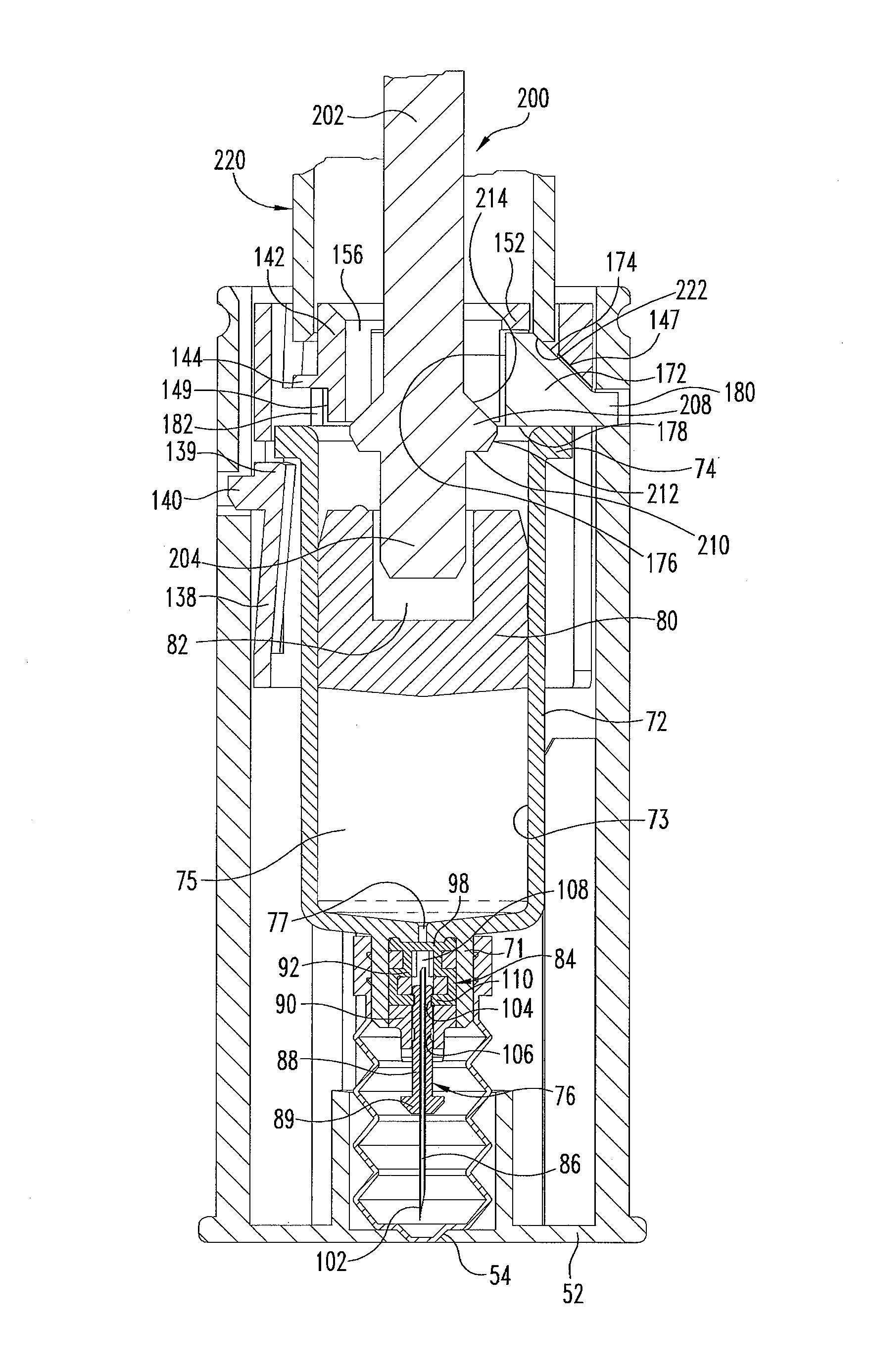
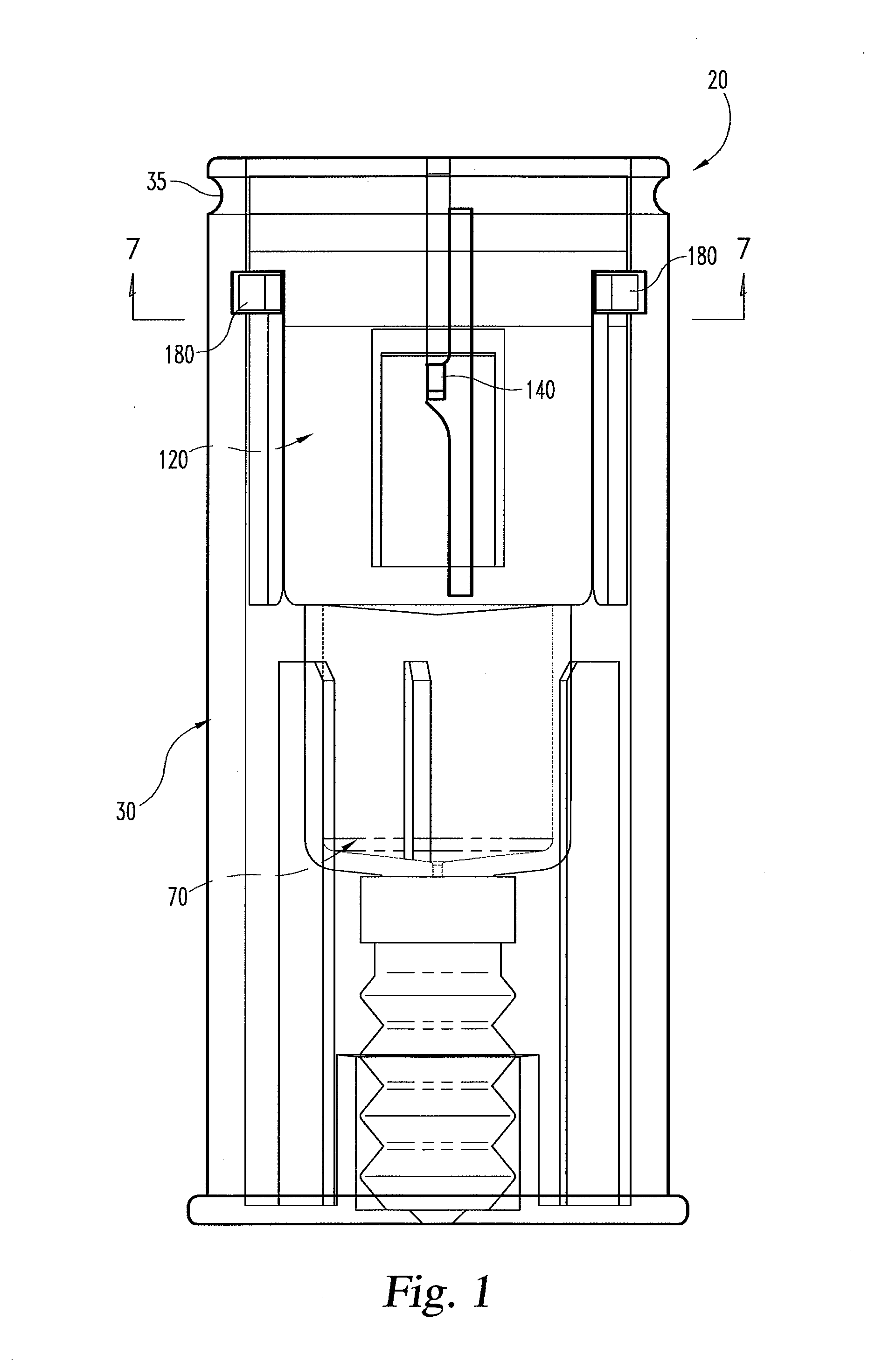
[0021]Referring now to FIG. 1, there is shown a first embodiment of a refill module of the present invention. The refill module, generally designated 20, is shown in its pre-use state. Refill module 20 is shown before any direct attachment or operative association with a reusable plunger assembly that interfaces with the module 20 to allow the medication contents of the module to be injected into a user through an injection needle of the module. Refill module 20 is described herein as preferably providing a single, pre-filled fixed dose of medicine, but such is illustrative as the module contents could be delivered over several doses, depending on the reusable plunger assembly and so long as an exposed needle is not problematic between doses.

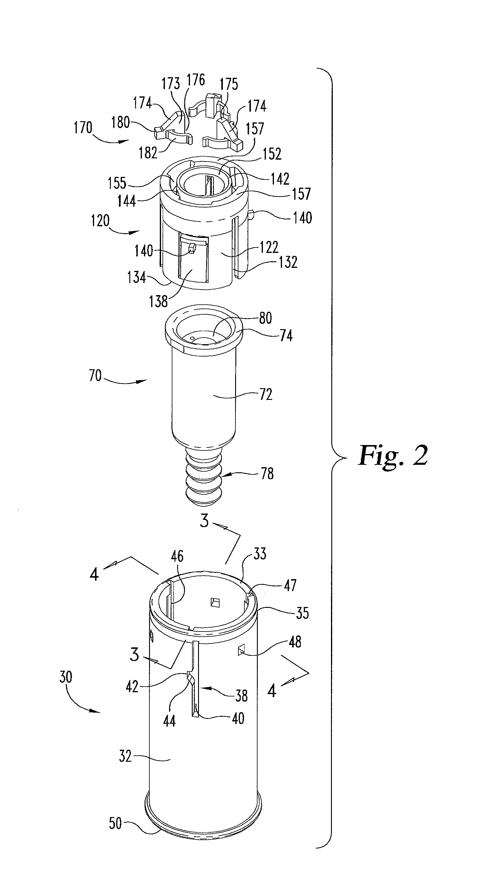
[0022]With additional reference to FIGS. 2-6, refill module 20 is assembled from a housing, generally designated 30, a syringe subassembly, generally designated 70, a carrier, generally designated 120, and a set of three latching elements, gener...


PUM


Abstract

A refill module for use with a plunger assembly and having a housing (30), a syringe subassembly (70), a carrier (120) and at least one latching element (170). The syringe subassembly is shiftable within the housing from a retracted position to an injecting position at which its injection tip projects beyond the housing end. The carrier has a passageway in which a plunger of a plunger assembly is insertable for advancement of a piston (80) of the syringe subassembly. The syringe subassembly is engagable by the carrier to be moved from its injecting position to a point at which the injection tip is retracted within the housing when the carrier shifts from a first axial position to a second axial position. The at least one latching element is shiftable relative to the carrier from a retracted arrangement to a latching arrangement such that a latch surface of the latching element restricts a size of the passageway to prevent plunger withdrawal. The carrier is liftable within the housing to retract the injection tip into the housing when the at least one plunger is retracted and a latch abutment surface of that plunger engages the latch surface. When the carrier reaches the second axial position, the at least one latching element is shiftable to move the latch surface clear of the latch abutment surface to allow withdrawal of the at least one plunger from the passageway without further lifting of the carrier.

Description

BACKGROUND OF THE INVENTION[0001]The present invention pertains to pharmaceutical injection devices, and, in particular, to a refill module containing medication that is used with a reusable plunger assembly.[0002]Patients suffering from a number of different diseases frequently must inject themselves with pharmaceuticals. A variety of devices have been proposed to facilitate these injections. One type of device is an automatic injection device or autoinjector. This type of device, when triggered by a user, typically automatically inserts into the user a needle of a syringe that prior to triggering was disposed within the device housing, and then automatically injects a dose of medication through that inserted needle.[0003]While automatic injection devices of this type may make the injection process more pleasant for some, such a device is more complex than a standard syringe. This complexity makes single use or disposable automatic injection devices more costly to manufacture than ...

Claims


Application Information

Patent Timeline
Patent Type & Authority Patents(United States)
IPC IPC(8): A61M5/315A61M5/20A61M5/32A61M5/24
CPCA61M5/31513A61M5/2033A61M5/326A61M5/3271A61M2005/206A61M2005/2073A61M2005/2474A61M2005/3247
Inventor FOURT, JESSE ARNOLDDAVIS-WILSON, JENNIFER ELLENYURCHENCO, JAMES R.
Owner ELI LILLY & CO
Why Eureka
Try Eureka