
Optical line termination in a passive optical network

a passive optical network and optical line technology, applied in data switching networks, multiplex communication, digital transmission, etc., can solve the problems of non-time sensitive functions such as added delay and jitter versus time-sensitive functions

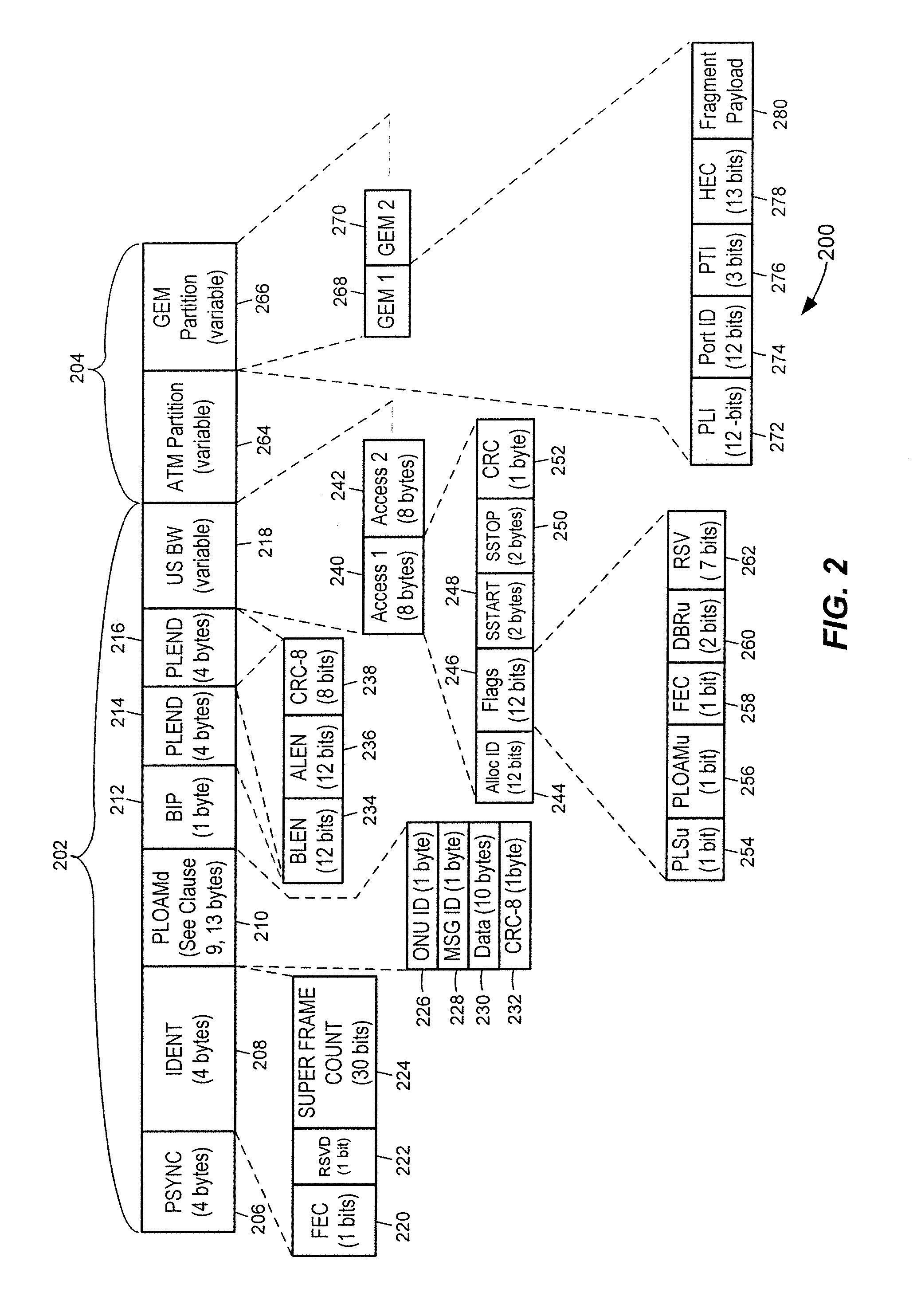
Active Publication Date: 2015-11-03
MARVELL ASIA PTE LTD
View PDF68 Cites 25 Cited by
  • Summary
  • Abstract
  • Description
  • Claims
  • Application Information

AI Technical Summary

Benefits of technology

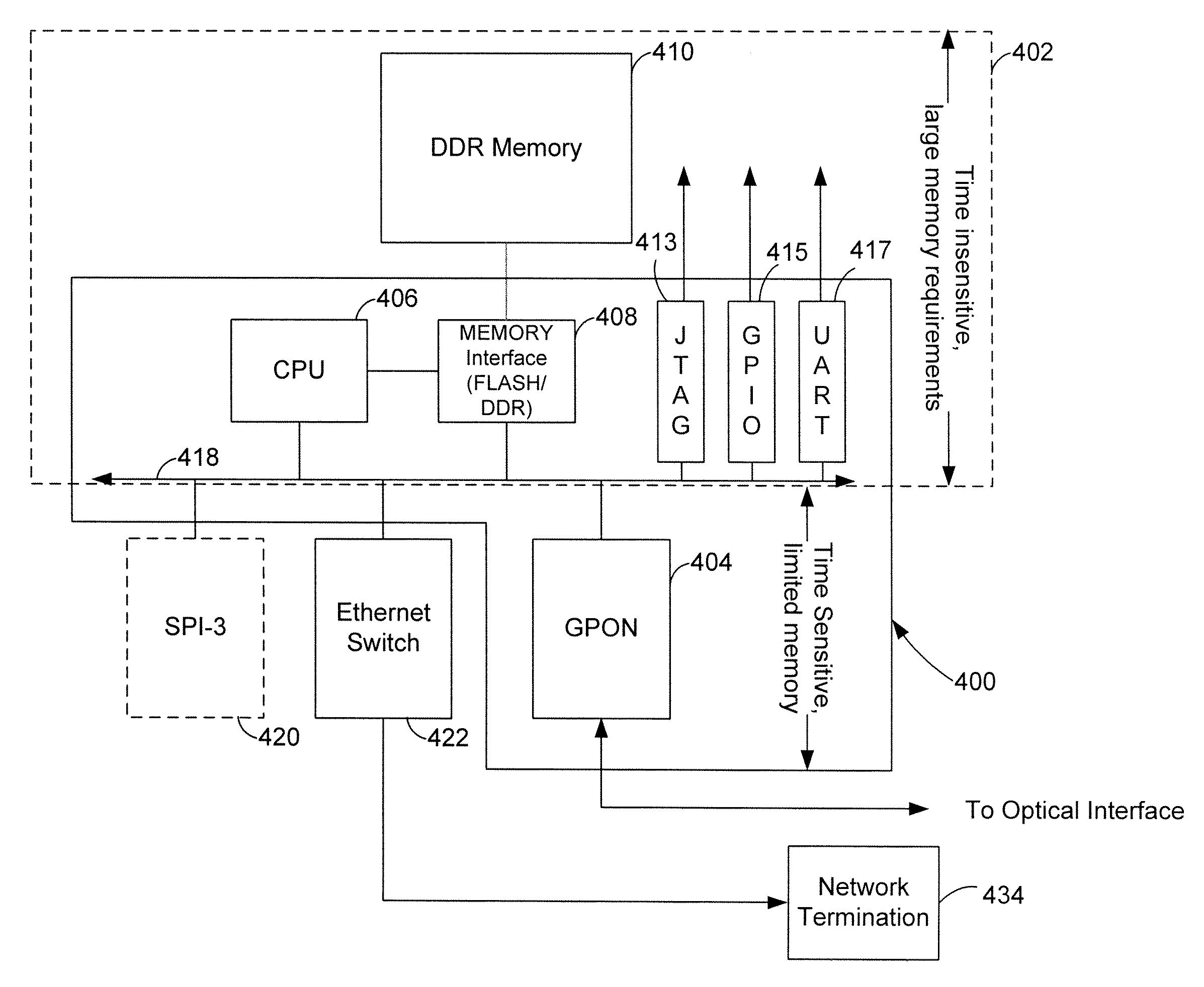
The patent describes a line termination unit integrated circuit for a passive optical network (PON) chip. The integrated circuit includes a receiver to receive an upstream transmission from a network termination unit, a transmitter to transmit a downstream transmission to the network termination unit, and an internal processor to process sub-fields within the overhead field of the upstream transmission. The integrated circuit also includes a system-on-a-chip (SoC) subsystem with an SoC processor and memory interface, and a distributed direct memory access engine to interconnect the integrated circuit with the SoC sub-system and directly access the memory. The method of processing the upstream transmission includes receiving the transmission, processing the overhead field, recovering the data frame, and providing the recovered data frame to a packet buffer external to the chip. The method of processing the downstream transmission includes receiving the packet data, assembling the overhead field, and transmitting the downstream transmission frame. The patent aims to improve the efficiency and reliability of data transmission in the PON network.

Problems solved by technology

However, non-time sensitive functions may include added delay and jitter versus time-sensitive functions.

Method used


Image

  • Optical line termination in a passive optical network
  • Optical line termination in a passive optical network
  • Optical line termination in a passive optical network

Examples


Embodiment Construction

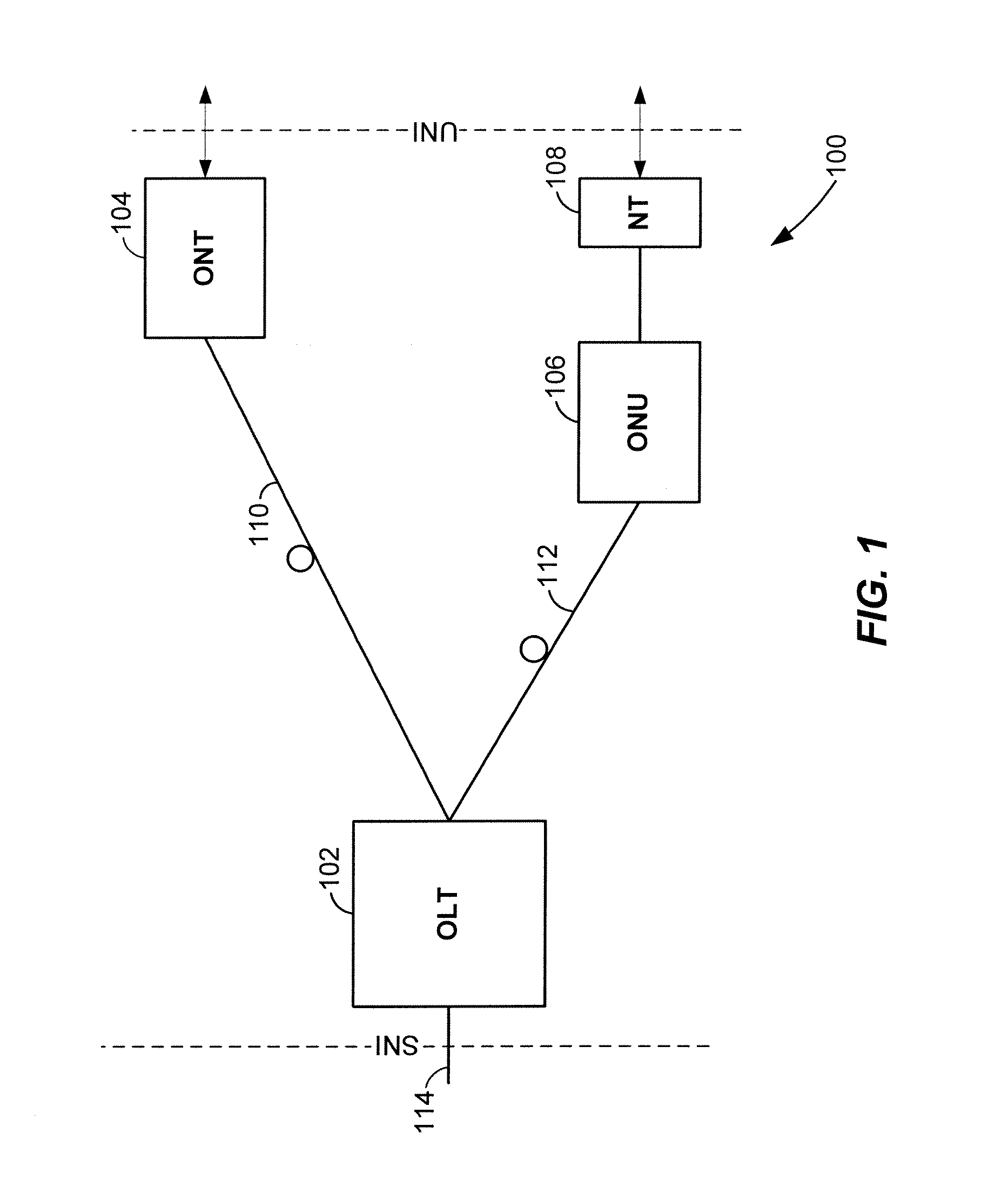
[0015]FIG. 1 is a block diagram of an example passive optical network 100 that includes an optical line termination (OLT) 102 coupled to an optical network terminal (ONT) 104 and an optical network unit (ONU) 106. Generally, the passive optical network 100 is a point-to-multipoint network, where the OLT 102 is provided as a service node interface, for example at a server or service provider, such as an internet service provider, television service provider, telephony service provider or other provider of network services. The ONT 104 and / or ONU 106 are each provided as an user node interface, for example at or near an end user. While the OLT 102 may be provided at the service provider site, the OLT 102 may also be provided as one of several OLTs within a distributed network, where each OLT is associated with corresponding ONUs 106 and / or ONTs 104.

[0016]As shown in FIG. 1, the OLT 102 is communicatively coupled to the ONT 104 via an optical fiber 110, and communicatively coupled to t...


PUM


Abstract

In a line termination unit integrated circuit in a point-to-multipoint network, a receiver receives an upstream transmission from a network termination unit within the point-to-multipoint network, a transmitter transmits a downstream transmission to a network termination unit within the point-to-multipoint network, and an internal processor operatively coupled to the receiver processes sub-fields within the overhead field of the upstream transmission. The internal processor is also operatively coupled to the transmitter to assemble the overhead field of the downstream transmission. The upstream transmission is an upstream transmission convergence frame format having an overhead field and a payload field, and the downstream transmission is a downstream transmission convergence frame format having an overhead field and a payload field.

Description

CROSS-REFERENCES TO RELATED APPLICATIONS[0001]The present application claims the benefit of U.S. Provisional Application No. 60 / 867,504, entitled “OLT ARCHITECTURE OVERVIEW,” filed on Nov. 28, 2006, which is hereby incorporated by reference herein in its entirety.FIELD OF TECHNOLOGY[0002]The present disclosure relates generally to line termination in point-to-multipoint networks, and more particularly, to optical line termination in a gigabit passive optical network.DESCRIPTION OF THE RELATED ART[0003]In point-to-multipoint networks, such as passive optical networks, the upstream and downstream transmissions are based on a transmission convergence frame format. The frame format generally includes an overhead field and a payload field. An optical line termination (OLT) unit provides an interface between the passive optical network and the backbone network of a service provider. The OLT is responsible managing optical network termination (ONT) units in the passive optical network, inc...

Claims


Application Information

Patent Timeline
IPC IPC(8): H04L12/28H04L7/00H04J3/16H04J14/00
CPCH04L7/0075H04L12/2861H04J3/1652H04J14/00H04L12/2898H04Q11/0067H04Q2011/0064
Inventor JOHNSTON, CESAR A.CHIANG, JOHN M.
Owner MARVELL ASIA PTE LTD
Learn More