
Large-aperture telephoto lens system

a telephoto lens and large aperture technology, applied in the field of large aperture telephoto lens systems, can solve the problems of difficult to achieve a high imaging quality, the effective diameter of the focusing lens group is too large for use, and the autofocus drive mechanism is burdened, so as to reduce the weight of the focusing lens group, reduce the burden, and achieve superior optical quality

Active Publication Date: 2015-10-13
RICOH IMAGING COMPANY
View PDF8 Cites 1 Cited by
  • Summary
  • Abstract
  • Description
  • Claims
  • Application Information

AI Technical Summary

Benefits of technology

[0009]The present invention has been devised in consideration of the above-discussed problems and provides a large-aperture telephoto lens system which can reduce the burden on the autofocus drive mechanism by appropriately setting the optical power balance between the lens groups of the optical system so as to miniaturize and reduce the weight of the focusing lens group, and by favorably correcting various aberrations such as spherical aberration that occur during a focusing operation to thereby achieve a superior optical quality.
[0010]Furthermore, the present invention achieves a superior optical quality by appropriately setting the arrangement, shape and refractive power of each lens element provided in a first lens group in an internal focusing telephoto lens system configured of a positive first lens group, a negative second lens group, and a positive third lens group, in that order from the object side, wherein the second lens group is used as a focusing lens group by moving in the optical axis direction during a focusing operation on an object at infinity to an object at a finite distance.
[0028]According to the present invention, a large-aperture telephoto lens system is achieved which can reduce the burden on the autofocus drive mechanism by appropriately setting the optical power balance between the lens groups of the optical system so as to miniaturize and reduce the weight of the focusing lens group, and achieves a superior optical quality by favorably correcting various aberrations such as spherical aberration that occur during a focusing operation.
[0029]Furthermore, according to the present invention, a superior optical quality is achieved by appropriately setting the arrangement, shape and refractive power of each lens element provided in a first lens group in an internal focusing telephoto lens system configured of a positive first lens group, a negative second lens group, and a positive third lens group, in that order from the object side, wherein the second lens group is used as a focusing lens group by moving in the optical axis direction during a focusing operation on an object at infinity to an object at a finite distance.

Problems solved by technology

However, if the diameter and the weight of the focusing lens group increase, the burden on the autofocus drive mechanism increases.
Furthermore, it also becomes difficult to attain a high imaging quality.
However, merely scaling down the optical system still results in the effective diameter of the focusing lens group being too big for use as a lens group for use in the above-described miniature camera.
Whereas, if attempts are made to reduce the lens diameters in order to reduce the burden on the autofocus drive mechanism, it becomes difficult to achieve a high imaging quality.
In each of the telephoto lens systems disclosed in Patent Literature 1 through 5, since the optical-power balance is set inappropriately in each lens group of the optical system, the movement amount of the focusing lens group during focusing is large, the effective aperture diameter of the focusing lens group is large and the weight of the focusing lens group is large, thereby increasing the burden on the autofocus drive mechanism, and correction of various aberrations, such as spherical aberration, that occur during a focusing operation becomes difficult, so that the optical quality deteriorates.
Furthermore, in the internal focusing telephoto lens systems disclosed in Patent Literature 1 through 5, since the spherical aberration correction and coma correction in the first lens group, which has a strong positive refractive power, are inappropriate, a high imaging quality cannot be achieved and the aperture diameter cannot be suitably enlarged.

Method used


Image

  • Large-aperture telephoto lens system
  • Large-aperture telephoto lens system
  • Large-aperture telephoto lens system

Examples


numerical embodiment 1

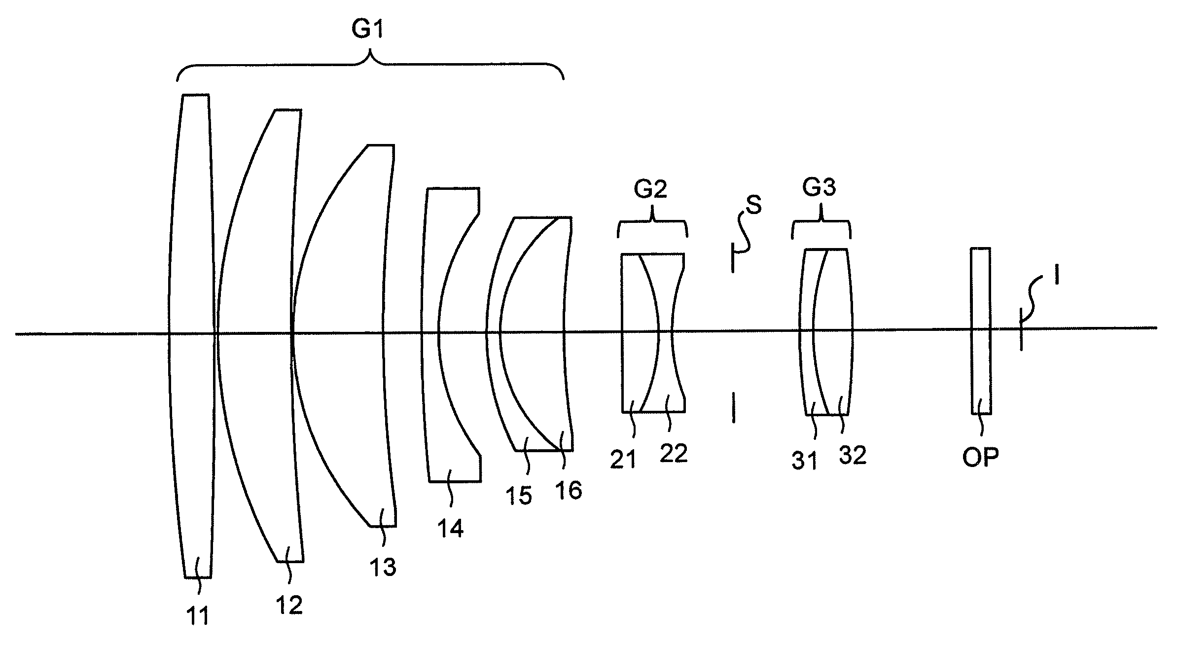
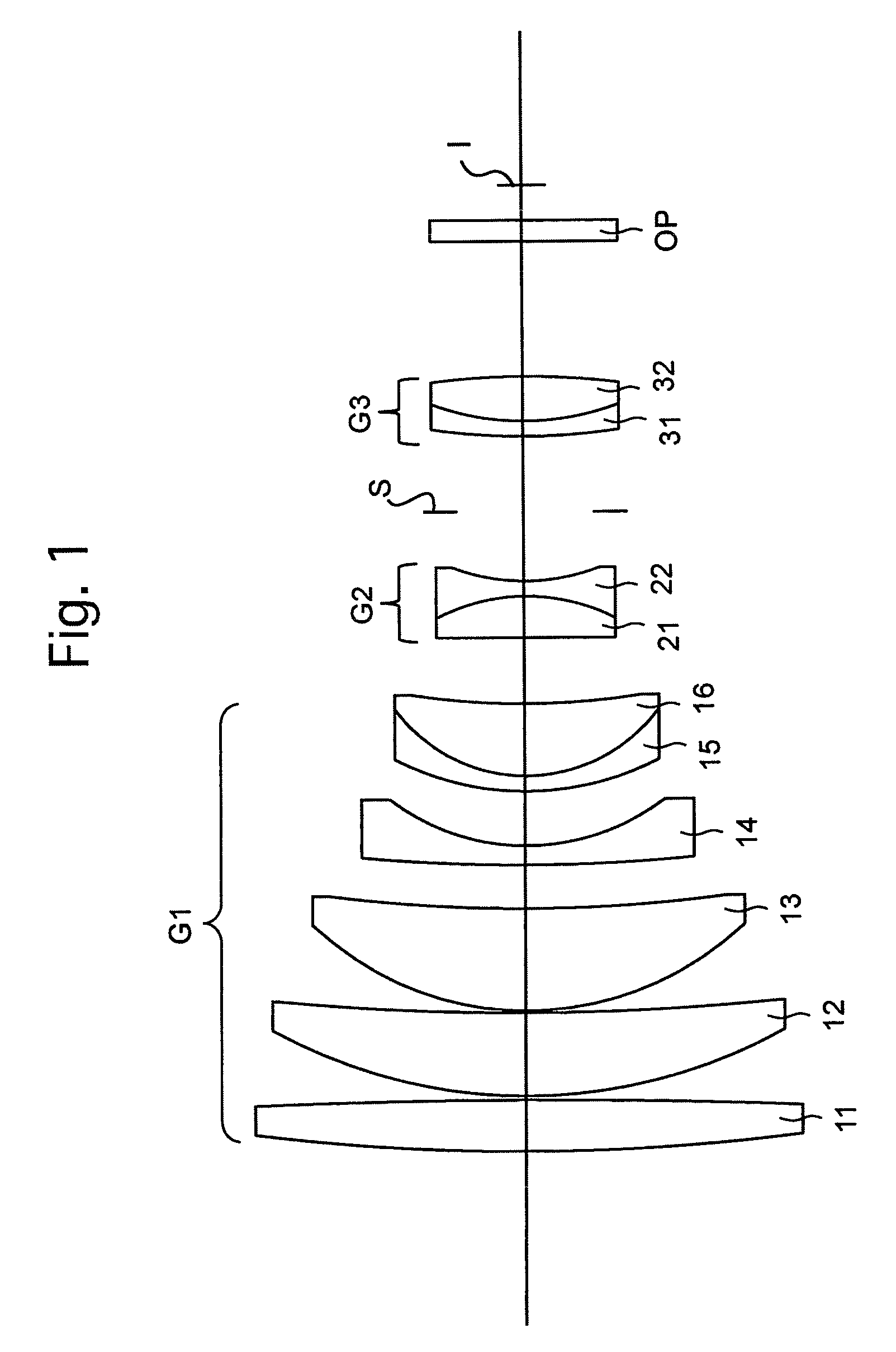
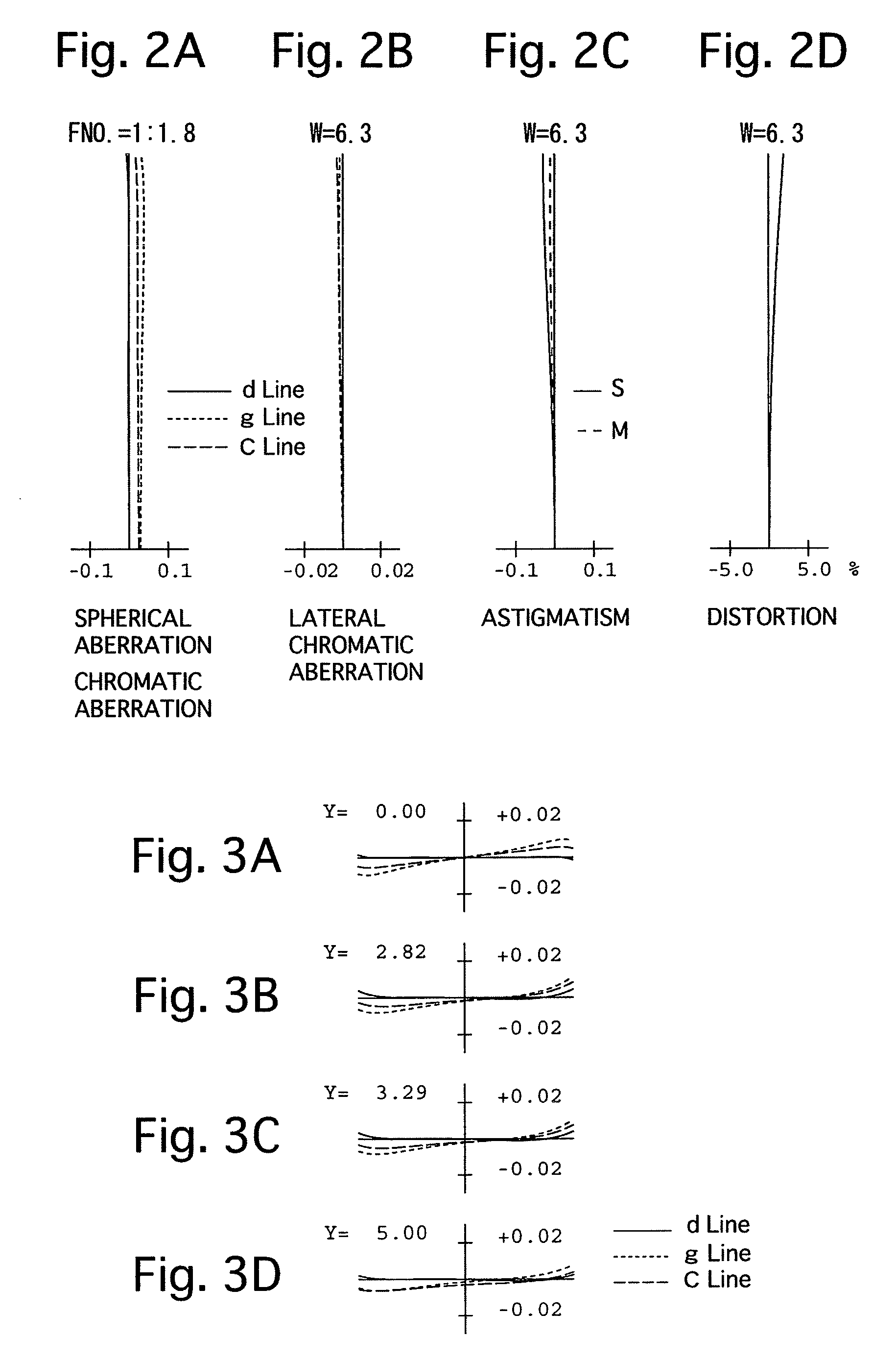
[0078]FIGS. 1 through 3D and Tables 1 and 2 show a first numerical embodiment of a large-aperture telephoto lens system according to the present invention. FIG. 1 shows a lens arrangement of the large-aperture telephoto lens system when focusing on an object at infinity. FIGS. 2A, 2B, 2C and 2D show various aberrations that occurred in the lens arrangement shown in FIG. 1. FIGS. 3A, 3B, 3C and 3D show various lateral aberrations that occurred in the lens arrangement shown in FIG. 1. Table 1 shows lens surface data, and Table 2 shows various data of the large-aperture telephoto lens system.

[0079]The large-aperture telephoto lens system according to the first numerical embodiment is configured of a positive first lens group G1, a negative second lens group G2, and a positive third lens group G3, in that order from the object side. A diaphragm S is provided between the second lens group G2 and the third lens group G3. An optical filter OP is provided in between the third lens group G3 ...

numerical embodiment 2

[0085]FIGS. 4 through 6D and Tables 3 and 4 show a second numerical embodiment of a large-aperture telephoto lens system according to the present invention. FIG. 4 shows a lens arrangement of the large-aperture telephoto lens system when focusing on an object at infinity. FIGS. 5A, 5B, 5C and 5D show various aberrations that occurred in the lens arrangement shown in FIG. 4. FIGS. 6A, 6B, 6C and 6D show various lateral aberrations that occurred in the lens arrangement shown in FIG. 4. Table 3 shows lens surface data, and Table 4 shows various data of the large-aperture telephoto lens system.

[0086]The lens arrangement of the second numerical embodiment is the same as that of the first numerical embodiment except for the following (1):

[0087](1) The negative lens element 31 of the third lens group G3 is a biconcave negative lens element.

[0088]

TABLE 3SURFACE DATASurf. No.RdN(d)ν(d) 175.2112.9731.4874970.4 2−1236.4400.200 332.9133.7781.4970081.6 4136.6560.100 517.0535.3491.4970081.6 688.7...

numerical embodiment 3

[0090]FIGS. 7 through 9D and Tables 5 and 6 show a third numerical embodiment of a large-aperture telephoto lens system according to the present invention. FIG. 7 shows a lens arrangement of the large-aperture telephoto lens system when focusing on an object at infinity. FIGS. 8A, 8B, 8C and 8D show various aberrations that occurred in the lens arrangement shown in FIG. 7. FIGS. 9A, 9B, 9C and 9D show various lateral aberrations that occurred in the lens arrangement shown in FIG. 7. Table 5 shows lens surface data, and Table 6 shows various data of the large-aperture telephoto lens system.

[0091]The lens arrangement of the third numerical embodiment is the same as that of the first numerical embodiment except for the following (1), (2) and (3):

[0092](1) The negative lens element 14 of the first lens group G1 is a biconcave negative lens element.

[0093](2) The positive lens element 16 of the first lens group G1 is a biconvex positive lens element.

[0094](3) The positive lens element 21 ...


PUM


Abstract

A large-aperture telephoto lens system includes a positive first lens group, a negative second lens group, and a positive third lens group, in that order from the object side, wherein the second lens group serves as a focusing lens group which is moved during focusing on an object at infinity to an object at a finite distance,wherein the following conditions (1) and (2) are satisfied:−4<f / f2<−3  (1), and1.3<f / f3<2.3  (2),wherein f designates the focal length of the entire large-aperture telephoto lens system, f2 designates the focal length of the second lens group, and f3 designates the focal length of the third lens group.

Description

BACKGROUND OF THE INVENTION[0001]1. Field of the Invention[0002]The present invention relates to a large-aperture telephoto lens system, and in particular, relates to an internal focusing large-aperture telephoto lens system which is suitable for use in an electronic still camera, in which a miniature solid-state image sensor is installed.[0003]2. Description of Related Art[0004]In the related art, an internal focusing telephoto lens system has been proposed with the objective of facilitating the focusing process and reducing the burden on the autofocus drive mechanism. In an internal focusing telephoto lens system, compared to a totally-telescoping lens system, it is possible to reduce movement distance of a focusing lens group that moves in the optical axis direction during a focusing operation and to reduce the weight of the focusing lens group. For example, in Japanese Unexamined Patent Publication No. H08-122629 (Patent Literature 1), Japanese Unexamined Patent Publication No. ...

Claims


Application Information

Patent Timeline
Patent Type & Authority Patents(United States)
IPC IPC(8): G02B9/20G02B13/02G02B9/64
CPCG02B13/02G02B9/64G02B9/20
Inventor ONOZAKI, TATSUYUKI
Owner RICOH IMAGING COMPANY
Learn More