Sub-assembly for an electromechanical brake actuator

a technology of brake actuator and sub-assembly, which is applied in the direction of electrodynamic brake system, electric vehicle, toothed gearing, etc., can solve problems such as the failure of the gear unit operation

Active Publication Date: 2015-09-29
LUCAS AUTOMOTIVE GMBH
View PDF24 Cites 14 Cited by
  • Summary
  • Abstract
  • Description
  • Claims
  • Application Information

AI Technical Summary

Benefits of technology

[0011]The fixing element may have a plate-like base member, in which an opening for receiving the drive device is provided at the first end. The plate-like base member can be provided with the internal-toothed wheel at the second end. The fixing element and the internal-toothed wheel may be constructed in two parts or integrally. Owing to the internal-toothed wheel being integrated into the fixing element in one piece, the number of individual parts of the subassembly is reduced, which has an advantageous effect on the weight, the compact structure, the production costs and the operational reliability of the subassembly.
[0012]According to one realization, the fixing element is constructed with an integrated internal-toothed wheel as a cast component. Cast components have the advantage that they can be mechanically loaded and can be produced in a cost-effective manner with narrow tolerances in terms of errors. Since the internal-toothed wheel is subjected to high mechanical loads (for example, vibrations), the securing of the internal-toothed wheel to the fixing plate or the housing assumes great significance. In particular, screwed securing arrangements may become loose over time and consequently reduce the service-life of the brake actuator.
[0013]The internal-toothed wheel may be part of a wobble plate mechanism, in which, for example, a wobble plate can be introduced. The internal-toothed wheel may also be part of a planet gear, in which additional components of the planet gear can be introduced. The internal-toothed wheel may comprise at least one internally toothed toothed wheel ring, in which at least one torque-transmitting planet wheel carrier of the gear device having a plurality of planet wheels thereon can be introduced. A multiple-stage construction of the planet gear may be advantageous in order to obtain a high power reduction without having to use an electric motor which has a more powerful torque (and is therefore heavier).
[0021]The planet wheels are preferably supported rotatably on the planet wheel carrier via the pin-like bearing shafts and the sun wheel via the centrally fitted first gear shaft. That common support of the sun wheel and planet wheels promotes close-fitting engagement of the gear wheels with each other so that the degree of efficiency and the wear properties of the planet gear are improved. Another advantage of a first gear shaft supported directly on the planet wheel carrier is that, for example, additional gear components of the gear device can be arranged on the planet wheel carrier via the first gear shaft. An operable subassembly of the gear device can thereby be constructed at the output side along the first gear shaft, whose gear components rest directly or indirectly on the planet wheel carrier.
[0024]According to a first realization, the second gear stage of the gear device may be constructed as a planet gear and the output-side gear element of the second gear stage as a planet wheel carrier. The two planet gears may be arranged in a rotatable manner successively along the first gear shaft. The first gear shaft may further receive in a supporting manner a sun wheel of the second gear stage and an output-side gear element of the first gear stage connected to the sun wheel in a torque-locking manner. An output-side subassembly of the gear device can thereby be produced and is distinguished by a compact construction and a high level of torque reduction.

Problems solved by technology

For example, already an external damage to the housing may result in the operational failure of the gear unit if it is supported directly on the housing.

Method used


Image

  • Sub-assembly for an electromechanical brake actuator
  • Sub-assembly for an electromechanical brake actuator
  • Sub-assembly for an electromechanical brake actuator

Examples


Embodiment Construction

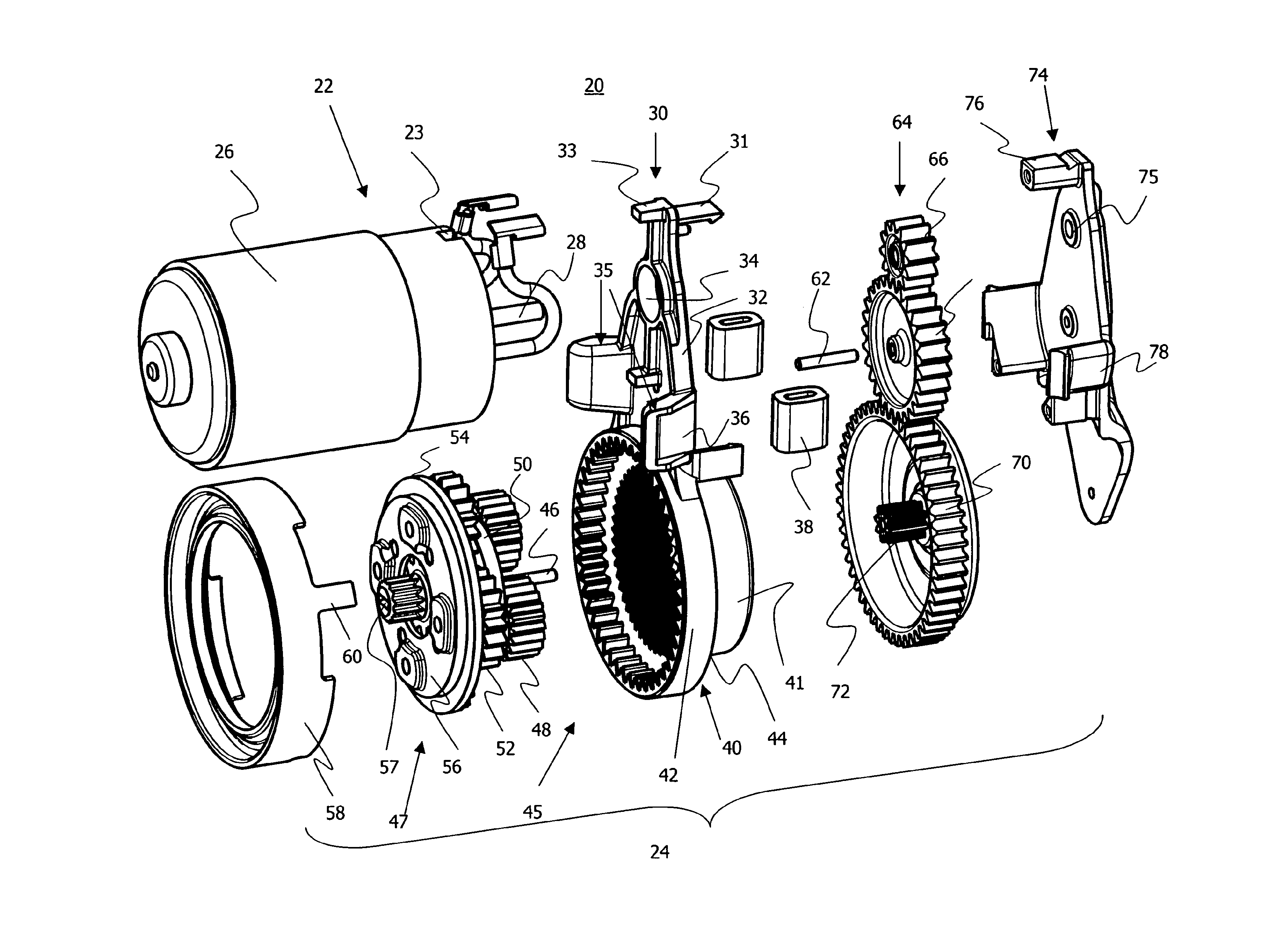
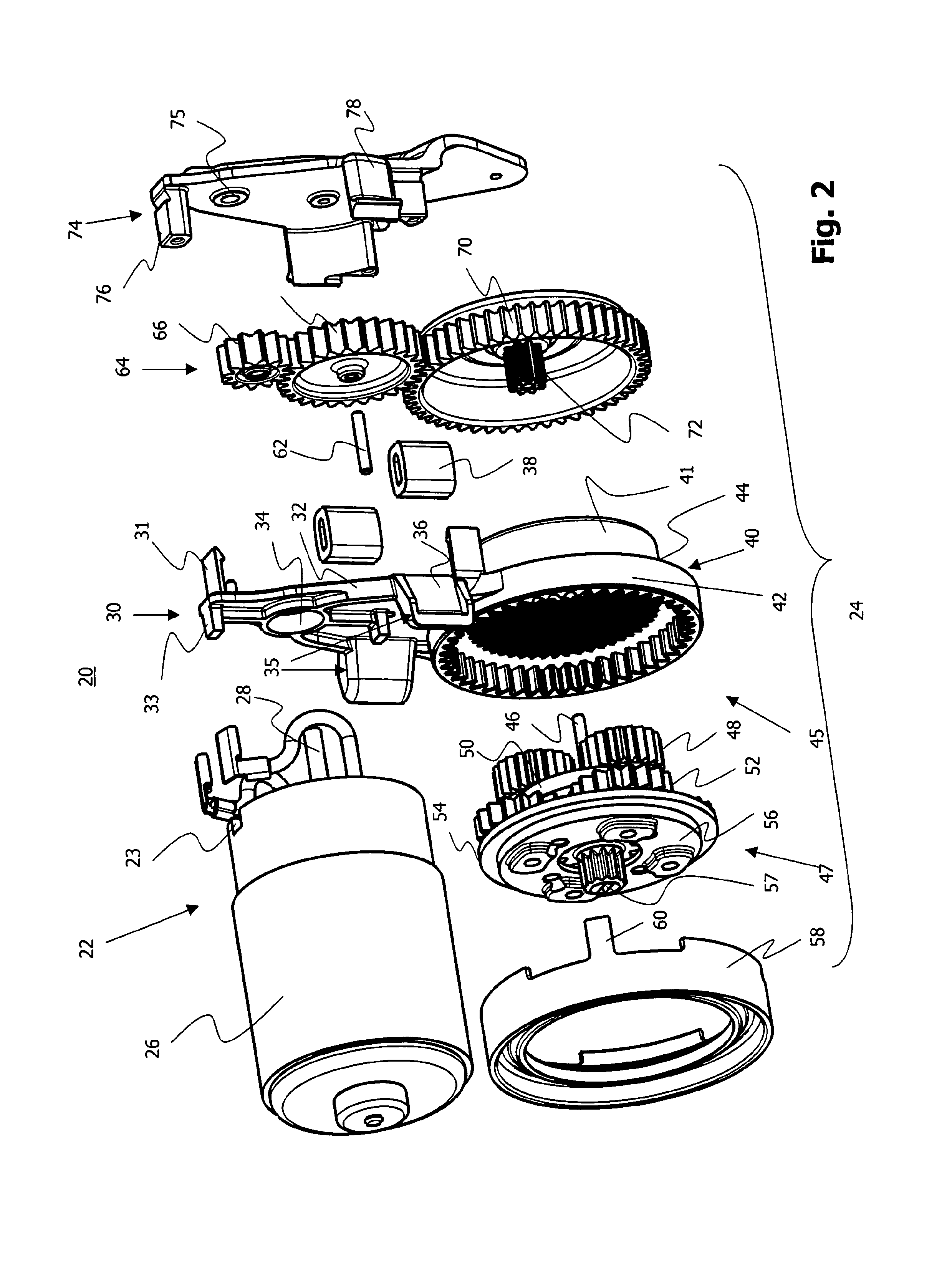
[0035]An embodiment of an assembly of an electromechanical brake actuator for an electrically operated parking brake is explained below. Corresponding elements in the Figures are given the same reference numerals. Terms such as “at the upper side” and “at the lower side” refer to the orientation of the assembly illustrated in the Figures. Of course, the electromechanical brake actuator may be orientated as desired (for example laid laterally) during installation.

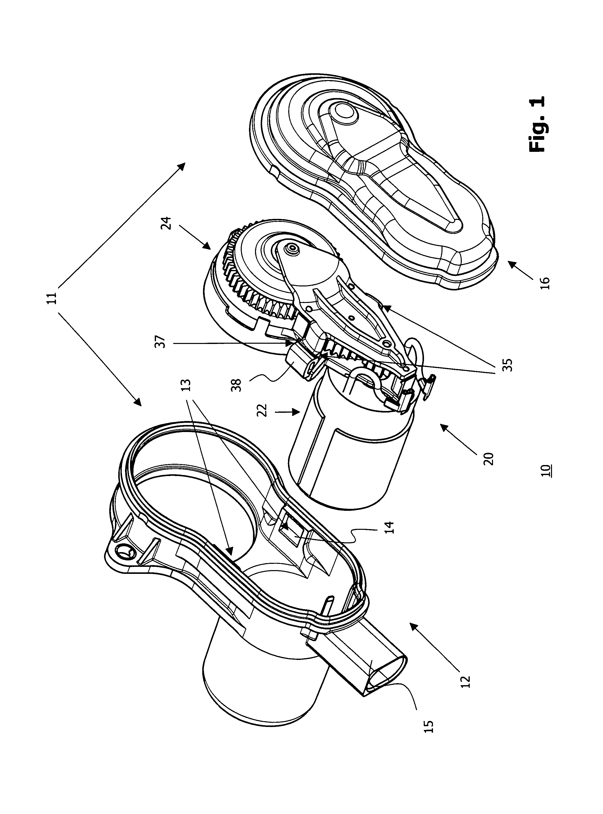
[0036]FIG. 1 is a perspective view of essential components of an assembly 10 of an electromechanical brake actuator. The assembly 10 comprises a housing 11 having a housing lower portion 12 and a housing upper portion 16 and a subassembly 20, which substantially comprises a drive device 22 and a gear device 24. Furthermore, the subassembly 20 has a first mounting device 35 which comprises two carriers 37 (only one carrier can be seen in FIG. 1 owing to the perspective view) which are each provided with a damping element 38 a...


PUM


Abstract

The invention relates to a subassembly for a brake actuator which is provided for an electromechanically operated parking brake. The subassembly comprises a drive device and gear device for generating and transmitting a torque to a brake device and a fixing element which secures the arrangement of the gear device relative to the drive device, an internal-toothed wheel of the gear device being integrated in the fixing element.

Description

CROSS-REFERENCE TO RELATED APPLICATIONS[0001]This application is a national stage of International Application No. PCT / EP2010 / 004544 filed Jul. 23, 2010, the disclosures of which are incorporated herein by reference in entirety, and which claimed priority to German Patent Application No. DE 10 2009 060 201.1 filed Dec. 23, 2009, the disclosures of which are incorporated herein by reference in entirety.BACKGROUND OF THE INVENTION[0002]The present invention relates to the field of motor vehicle brakes. More precisely, the invention relates to an improved construction of a subassembly of a brake actuator which is provided for an electromechanically operated parking brake or an electromechanically operated service brake.[0003]Electrically operated parking brakes are used increasingly often in motor vehicles. They have the advantage that they can be controlled with modern on-board electronic systems, thereby opening up new possibilities for the use of parking brakes in a motor vehicle. F...

Claims


Application Information

Patent Timeline
Patent Type & Authority Patents(United States)
IPC IPC(8): F16D21/08F16D65/18F16D65/00F16H1/46F16D121/24F16D121/26F16D125/48F16D125/50
CPCF16D65/18F16D65/0006F16D2121/24F16D2121/26F16D2125/48F16D2125/50F16H1/46
Inventor GIERING, WILFRIED
Owner LUCAS AUTOMOTIVE GMBH
Why Eureka
Try Eureka