Cathode housing suspension of an electron beam device

a technology of cathode housing and electron beam, which is applied in the manufacture of electrode systems, electric discharge tubes/lamps, nuclear engineering, etc., can solve the problems of stability, durability and longevity, affecting the longevity of the device, etc., and achieve the effect of reducing the risk of generation

Active Publication Date: 2015-09-22
TETRA LAVAL HLDG & FINANCE SA
View PDF23 Cites 0 Cited by
  • Summary
  • Abstract
  • Description
  • Claims
  • Application Information

AI Technical Summary

Benefits of technology

[0006]One advantage of a suspension in accordance with the present embodiment is that it facilitates aligned mounting of cathode housing. In particular it enables perfect positioning of the cathode housing in relation to the tube body without the need of machining constructional details with overly small tolerances. This in turn enables a simplified production of components, and a faster assembly of the device. The resulting suspension will be flexible in regard of its assembly, yet rigid in its assembled state. Even small deviations in the position of the cathode housing may have considerable impact on the performance of the electron-beam device. It may for instance affect the beam profile, and alterations in the beam profile may in turn affect the longevity of the device.
[0007]In one or more embodiments the connector end may comprise concentrically arranged cylindrical connector elements separated by annular ceramic spacers, wherein the ceramic spacers are arranged in a staggered fashion, such that adjacent spacers are shifted in the longitudinal direction in relation to each other, which results in a number of advantages listed in the detailed description. In further embodiments where every other ceramic spacer is aligned in the longitudinal direction the stability of the suspension is even further increased.
[0008]In one or more embodiments the biasing means comprises a plate spring arranged between the attachment end and the socket. The plate spring will provide a reliable biasing means, which may easily be localized in the adequate position, e.g. by having openings through which the screws and bolts may extend.
[0011]In order to decrease the risk of generation of excessive electric field strength and the generation of sparks the socket may have a curved surface on a side remote to the cathode housing.

Problems solved by technology

Within the field of sterilization of a web of packaging material, performance factors such as stability, durability and longevity are key issues, once the quality of the sterilization is ensured.
It may for instance affect the beam profile, and alterations in the beam profile may in turn affect the longevity of the device.

Method used


Image

  • Cathode housing suspension of an electron beam device
  • Cathode housing suspension of an electron beam device
  • Cathode housing suspension of an electron beam device

Examples


Embodiment Construction

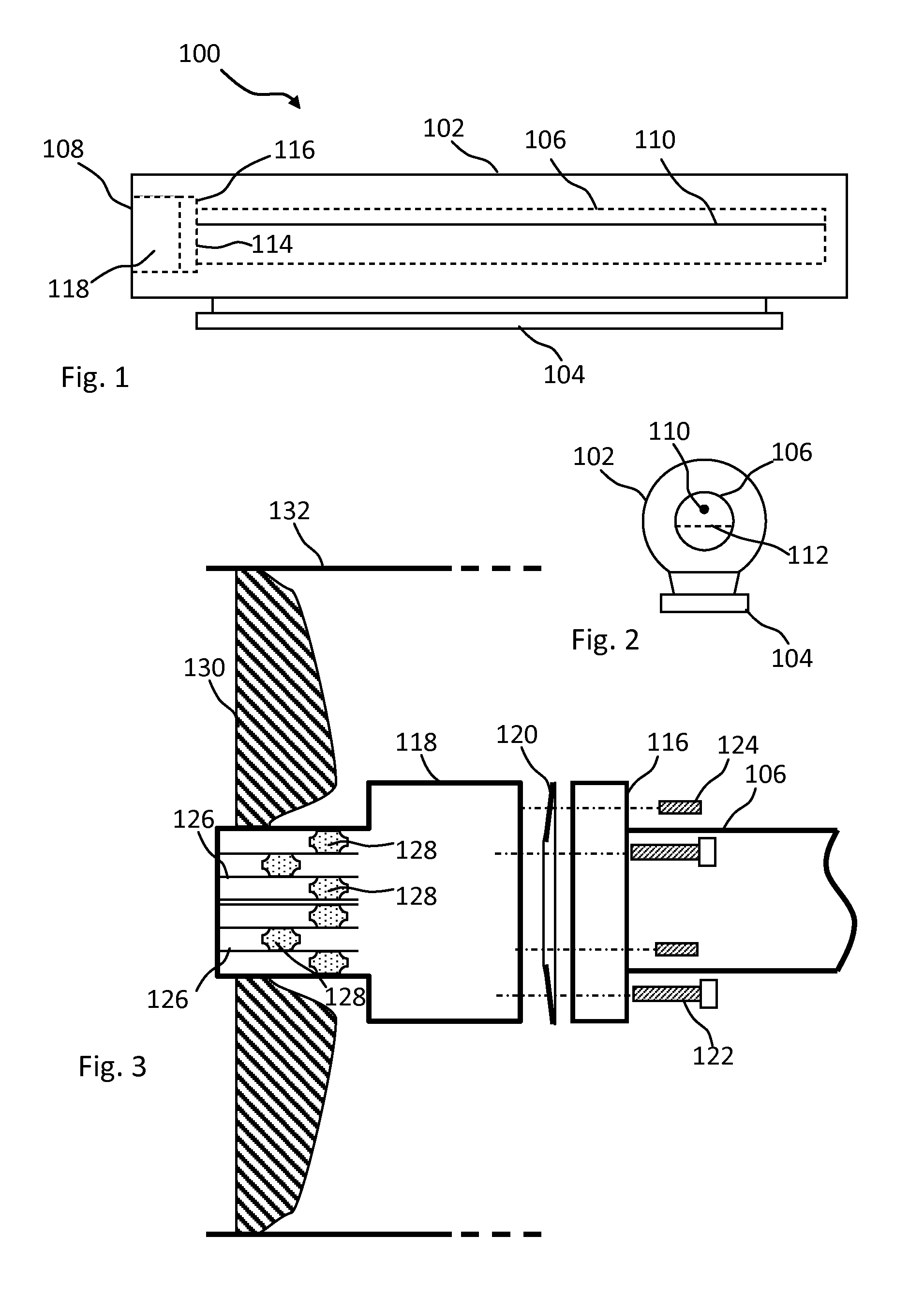
[0018]FIG. 1 is a schematic side view of an electron beam device which may comprise a suspension in accordance with one embodiment of the present invention.

[0019]FIG. 2 is a schematic cross section of the electron beam device of FIG. 1.

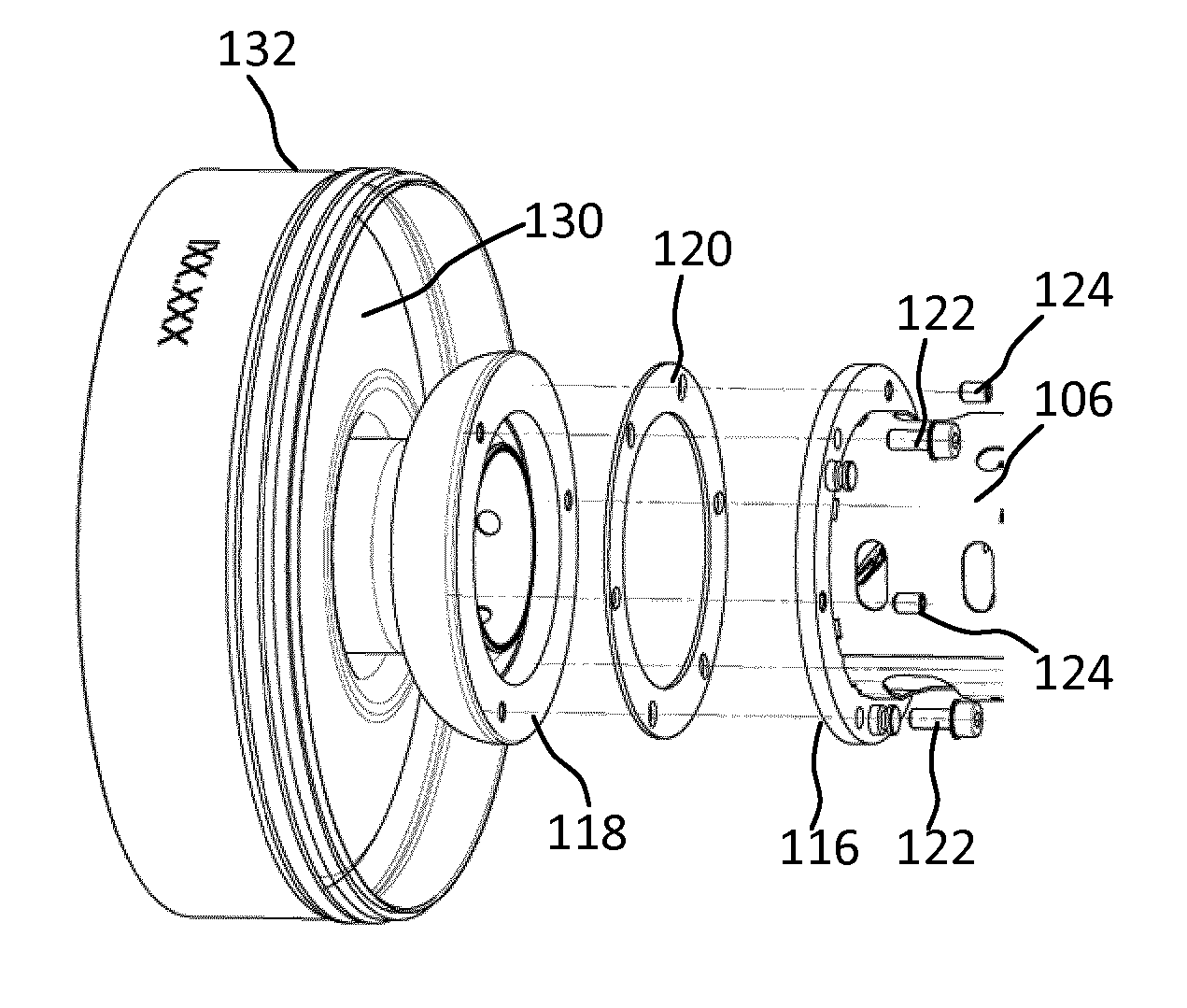
[0020]FIG. 3 is a schematic exploded view from the side of a suspension in accordance with one embodiment of the present invention.

[0021]FIG. 4 is an exploded view similar to FIG. 3, yet in perspective and in some more detail.

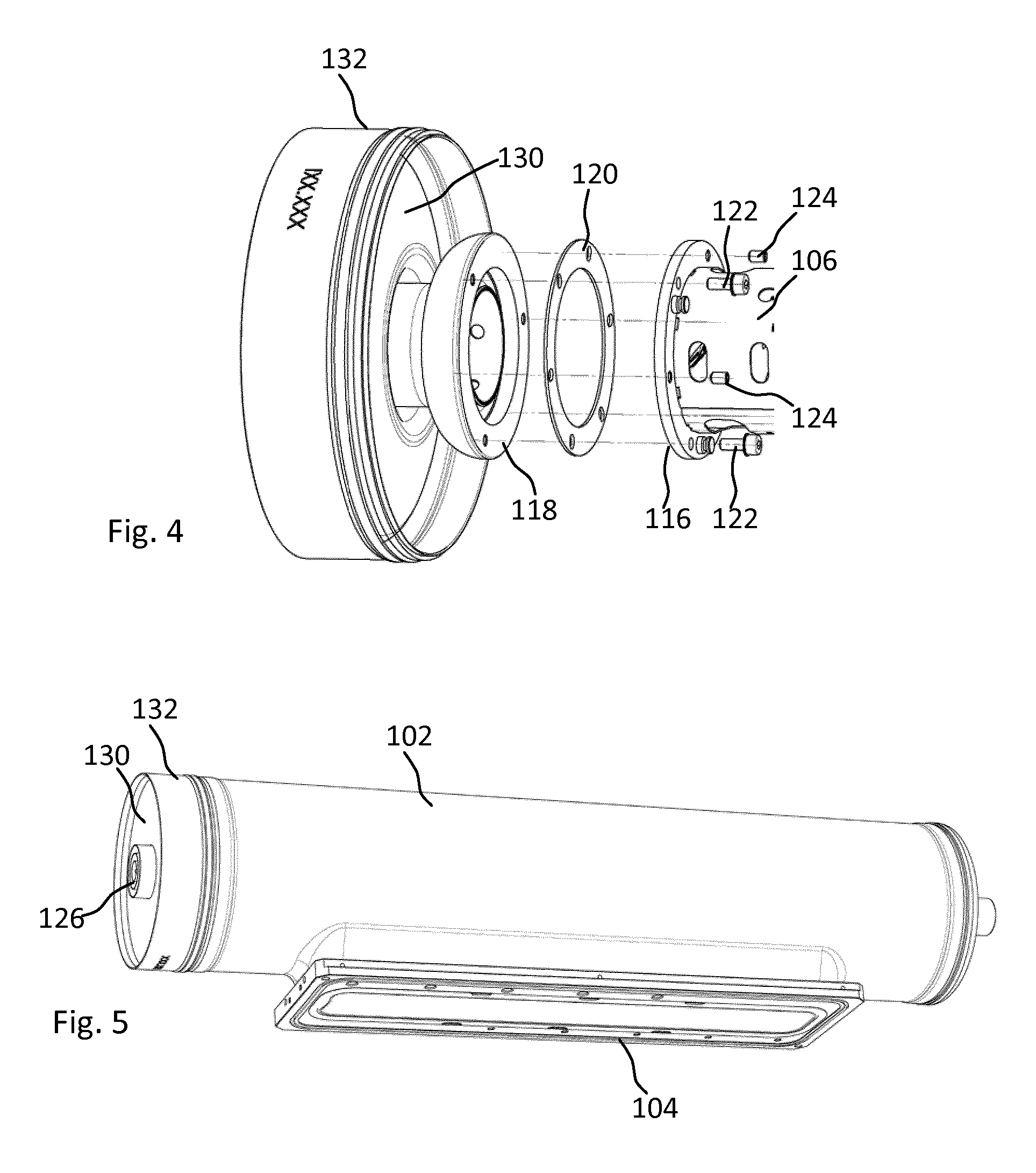
[0022]FIG. 5 is a perspective view of an electron beam device similar to FIG. 1 yet in some more detail.

DETAILED DESCRIPTION

[0023]FIG. 1 illustrates a side view of an electron beam device according to a first embodiment of the present invention. The purpose of the drawing is simply to illustrate the basic components of an electron beam device, and it should be emphasized that the purpose is not to provide a true constructional drawing or in any other way limit the present invention.

[0024]The electron beam device 100 of FIG. 1 com...


PUM


Abstract

A cathode-housing suspension of an electron beam device having a tubular body of elongate shape with an exit window extending in the longitudinal direction and a connector end in one end of the tubular body is disclosed. The electron beam device further comprises a cathode housing having an elongate shape and comprising a free end and an attachment end remote to the free end, and the attachment end comprises an outwardly extending flange provided with threaded openings for set screws and non-threaded openings for attachment bolts, for attaching the attachment end to a corresponding socket of the tubular body, wherein a mechanism configured to bias the attachment end away from the socket are arranged in the tubular body.

Description

TECHNICAL BACKGROUND[0001]The present invention relates to an electron beam device (EBD), and in particular to an EBD with improved properties in relation to a cathode housing thereof.[0002]A typical EBD comprises a vacuum tight body inside which a cathode housing is arranged. The cathode housing comprises a filament which is heated by a current in order for electrons to be produced. The thus produced electrons are accelerated by means of a high-voltage potential and exits through an exit window of the body, typically a thin window foil supported by a support grid. Electron beam devices may be used for several purposes, such as curing of paint or adhesives, or sterilisation of volumes or surfaces. Depending on the application properties such as acceleration voltage, beam profile, shape of the EBD will vary. The teachings of the present invention may advantageously be applied to EBD:s used for sterilization of a web of packaging material, since it may significantly improve the perfor...

Claims


Application Information

Patent Timeline
Patent Type & Authority Patents(United States)
IPC IPC(8): H01J1/88H01J33/02H01J9/36G21K5/02
CPCH01J1/88G21K5/02H01J9/36H01J33/02
Inventor WITTWER, HANSHOSTETTLER, URSREUSSER, HANSWABER, TONI
Owner TETRA LAVAL HLDG & FINANCE SA
Why Eureka
Try Eureka