
In-wheel actuator and in-wheel assembly comprising the same

a technology of in-wheel actuator and in-wheel assembly, which is applied in the direction of gearing, magnetic circuit rotating parts, magnetic circuit shape/form/construction, etc., can solve the problems of affecting endurance and performance the temperature of the decelerator may exceed a limited operating temperature, and the limit to reducing the size of the driving motor, etc., to achieve the effect of reducing the rotational for

Inactive Publication Date: 2015-09-22
SAMSUNG ELECTRONICS CO LTD
View PDF18 Cites 3 Cited by
  • Summary
  • Abstract
  • Description
  • Claims
  • Application Information

AI Technical Summary

Benefits of technology

This patent describes a decelerator for an in-wheel actuator that reduces the speed of a rotating force from a motor. The decelerator is made up of a housing and a part that reduces the force inside the housing. The technical effect is to create a smoother and more efficient actuator system for vehicles.

Problems solved by technology

Hybrid vehicles and electric vehicles have gained more popularity due to harmful environmental effects from air pollution and shortage of fossil fuels.
However, there is a limit to reducing the size of the driving motor, since a high output torque is needed for driving a vehicle.
Therefore, if the heat of the driving motor is transferred to the decelerator, the temperature of the decelerator may exceed a limited operating temperature.
Thus, endurance and performance of the driving motor may be affected.

Method used


Image

  • In-wheel actuator and in-wheel assembly comprising the same
  • In-wheel actuator and in-wheel assembly comprising the same
  • In-wheel actuator and in-wheel assembly comprising the same

Examples


Embodiment Construction

[0023]The following description is provided to assist the reader in gaining a comprehensive understanding of the methods, apparatuses, and / or systems described herein. Accordingly, various changes, modifications, and equivalents of the methods, apparatuses, and / or systems described herein will be suggested to those of ordinary skill in the art. Also, descriptions of well-known functions and constructions may be omitted for increased clarity and conciseness.

[0024]Throughout the drawings and the detailed description, unless otherwise described, the same drawing reference numerals will be understood to refer to the same elements, features, and structures. The relative size and depiction of these elements may be exaggerated for clarity, illustration, and convenience.

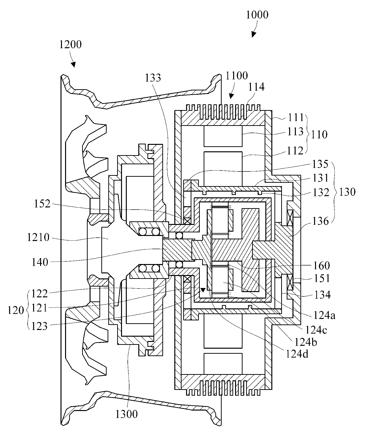
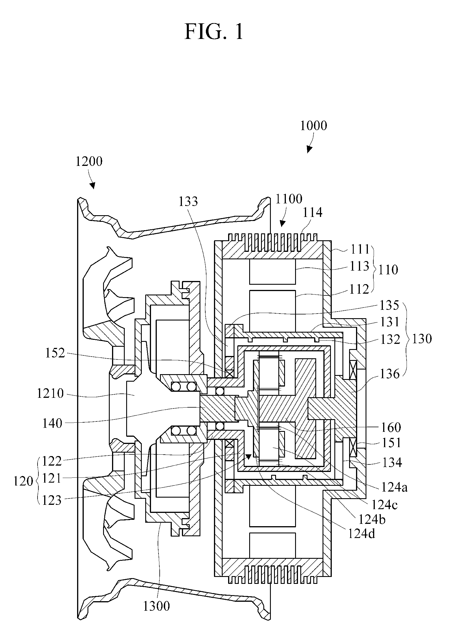
[0025]FIG. 1 is a cross-sectional view illustrating an in-wheel assembly according to an exemplary embodiment.

[0026]Referring to FIG. 1, an in-wheel assembly 1000 includes an in-wheel actuator 1100 and a wheel 1200.

[0027]The...


PUM


Abstract

An in-wheel assembly is provided, and the in-wheel assembly includes an in-wheel actuator and a wheel. The in-wheel actuator includes a driving motor; a decelerator which is disposed inside the driving motor and configured to reduce a rotational speed of the driving motor; and a hollow shaft which is disposed inside the driving motor and configured to transfer a rotational force of the driving motor to the decelerator, which is accommodated in a hollow of the hollow shaft, and circulates fluid inside of the driving motor with respect to a surface of the decelerator when driven to rotate by the driving motor. The wheel accommodates the in-wheel actuator and receives a rotational speed reduced by the decelerator to rotate.

Description

CROSS-REFERENCE TO RELATED APPLICATION[0001]This application claims priority from Korean Patent Application No. 10-2012-0100094, filed on Sep. 10, 2012, in the Korean Intellectual Property Office, the entire disclosure of which is incorporated herein by reference for all purposes.BACKGROUND[0002]1. Field[0003]The following description relates to an in-wheel actuator applicable to a vehicle, such as an electric automobile, which is driven with electrical power, and an in-wheel assembly comprising the same.[0004]2. Description of the Related Art[0005]Hybrid vehicles and electric vehicles have gained more popularity due to harmful environmental effects from air pollution and shortage of fossil fuels. A hybrid vehicle mainly uses an internal-combustion engine to generate power and uses an electric motor as an auxiliary power source. An electric vehicle uses an electric motor as a main power source.[0006]With the development of technologies for batteries and motors, it is expected that e...

Claims


Application Information

Patent Timeline
Patent Type & Authority Patents(United States)
IPC IPC(8): F16H57/04B60K7/00F16C3/02H02K7/116H02K5/18H02K7/14H02K9/08B60K17/04H02K7/102H02K1/32
CPCB60K7/0007F16C3/02F16H57/0412H02K5/18H02K7/116H02K7/14H02K9/08B60K17/046B60K2007/0038B60K2007/0092H02K1/32H02K7/102Y02T10/641Y10T464/10B60L3/0061B60L15/20B60L15/2054B60L2220/44B60L2240/12B60L2240/36B60L2240/421B60L2240/423B60L2240/425B60L2220/50Y02T10/72Y02T10/64Y02T10/70F16D2300/0214F16H37/04B60K7/00B60L50/50
Inventor PARK, TAE-SANG
Owner SAMSUNG ELECTRONICS CO LTD
Learn More