Control and regulation method for an internal combustion engine having a common rail system

a technology of internal combustion engine and rail system, which is applied in the direction of braking system, position/direction control, brake action initiation, etc., can solve the problems of difficult control of load reduction events, difficulty in adjusting the method, and inability to adjust the pressure in the rail system

Active Publication Date: 2015-09-15
ROLLS ROYCE SOLUTIONS GMBH
View PDF19 Cites 0 Cited by
  • Summary
  • Abstract
  • Description
  • Claims
  • Application Information

AI Technical Summary

Benefits of technology

The invention aims to address the problem of unstable rail pressure in a partial load reduction. It eliminates the cause of the oscillations and ensures a more uniform behavior of the rail pressure. This prevents unintended opening of the passive pressure control valve and enables stable rail pressure both in the case of a complete and partial load rejection, without the need for additional sensors or changes in the electronic engine control unit. The invention is cost-neutral and provides the desired results.

Problems solved by technology

Due to the high dynamic response, a load reduction is an event that is difficult to control from the standpoint of automatic control engineering, since after a load reduction, the rail pressure can rise with a pressure gradient of up to 4000 bars / second.
In practice, however, it was found that the method is still not optimal in the case of a partial load reduction.
Under unfavorable conditions, pressure oscillations in the rail can arise, which are caused by several successive changes from closed-loop control to open-loop control with temporary PWM assignment.

Method used


Image

  • Control and regulation method for an internal combustion engine having a common rail system
  • Control and regulation method for an internal combustion engine having a common rail system
  • Control and regulation method for an internal combustion engine having a common rail system

Examples


Embodiment Construction

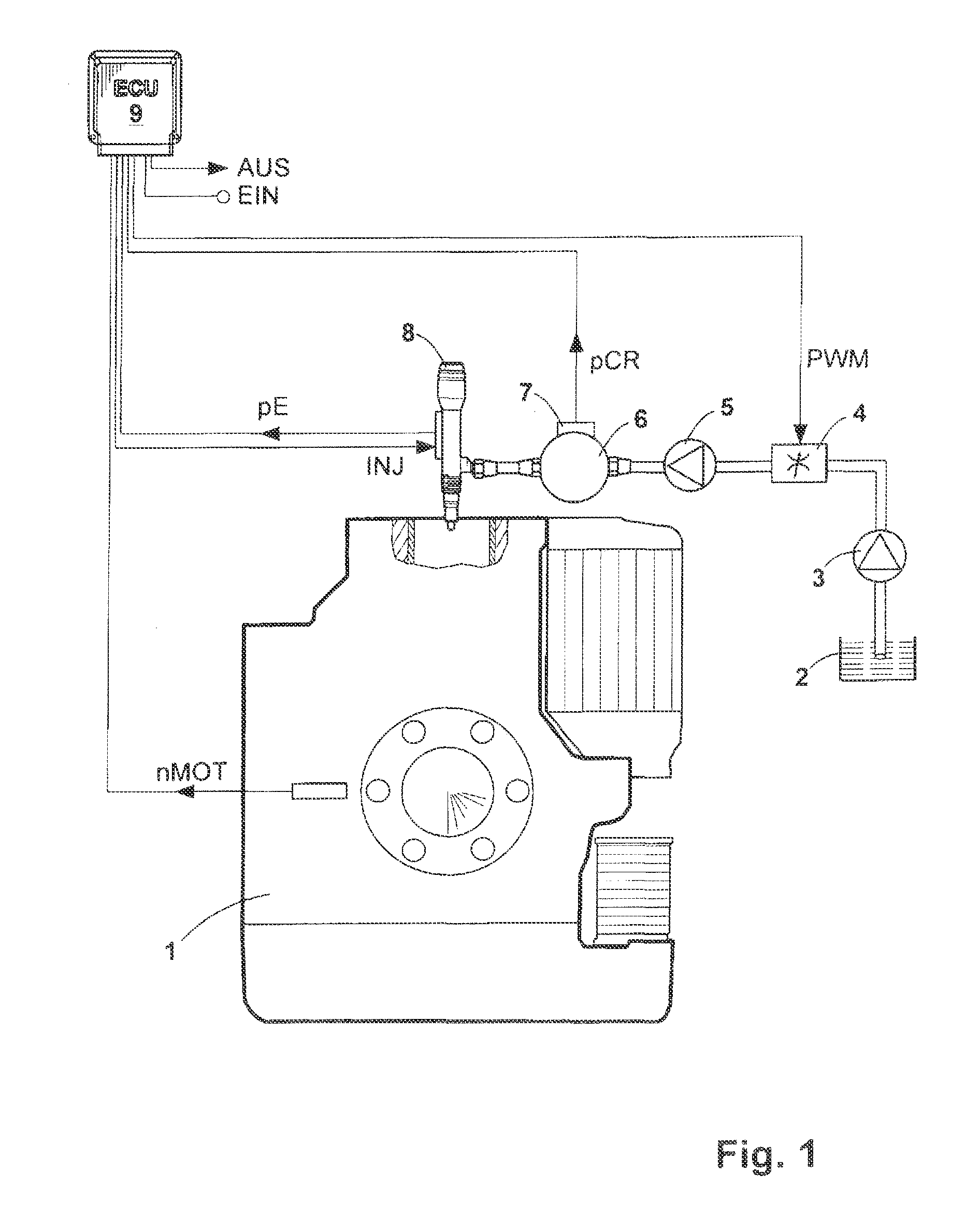
[0017]FIG. 1 shows a block diagram of an electronically controlled internal combustion engine 1 with a common rail system. The internal combustion engine 1 powers an emergency power generating unit (not shown). The common rail system comprises the following mechanical components: a low-pressure pump 3 for delivering fuel from a fuel tank 2, a suction throttle 4 for controlling the volume flow, a high-pressure pump 5, a rail 6, and injectors 8 for injecting fuel into the combustion chambers of the internal combustion engine 1.

[0018]The internal combustion engine 1 is controlled by an electronic engine control unit 9 (ECU). Input variables of the electronic engine control unit 9 shown in FIG. 1 are the rail pressure pCR, which is detected by a pressure sensor 7, the engine speed nMOT, and a variable EIN. The variable EIN is representative of other input signals, for example, input signals for the oil temperature or fuel temperature. The output variables of the electronic engine contro...


PUM


Abstract

The invention relates to a control and regulation method for an internal combustion engine (1) having a common rail system wherein the rail pressure (pCR) is regulated in normal operation in that an offset of the rail pressure (pCR) is calculated and a PWM signal (PWM) is determined for activating the control process via a pressure controller based on the offset, wherein a load rejection when the rail pressure (pCR) exceeds a limit and wherein upon recognition of the load rejection, the rail pressure (pCR) is controlled in that the PWM signal (PWM) is temporarily set to a PWM value that is higher compared to normal operation via a PWM parameter. The invention is characterized in that the threshold for activation of the temporary PWM parameter is calculated in dependence on the gradient of a power-determining signal.

Description

[0001]The present application is a 371 of International application PCT / EP2009 / 007988 filed Nov. 9, 2009, which claims priority of DE 10 2008 058 721.4, filed Nov. 24, 2008, the priority of these applications is hereby claimed and these applications are incorporated herein by reference.BACKGROUND OF THE INVENTION[0002]The invention concerns a method for the open-loop and closed-loop control of an internal combustion engine with a common rail system, in which, during normal operation, the rail pressure is controlled by closed-loop control, and, when a load reduction is detected, a change is made from closed-loop control to open-loop control, wherein, during the open-loop control operation, the PWM signal is temporarily set to a PWM value that is higher than in normal operation in order to load the controlled system.[0003]In a common rail system, a high-pressure pump delivers the fuel from a fuel tank to a rail. The admission cross section to the high-pressure pump is determined by a ...

Claims


Application Information

Patent Timeline
IPC IPC(8): F02D41/38F02D41/12F02D41/14
CPCF02D41/3845F02D41/3863F02D41/123F02D41/1479F02D2041/141F02D2250/04
Inventor DOLKER, ARMIN
Owner ROLLS ROYCE SOLUTIONS GMBH
Why Eureka
Try Eureka