
Screw for fixing vertebra

a screw and vertebra technology, applied in the field of screw fixing vertebrae, can solve the problems of serious deformation, pain, degenerative disease, etc., and achieve the effect of increasing the degree of freedom and moving smoothly

Active Publication Date: 2015-09-15
L&K BIOMED CO LTD
View PDF1 Cites 5 Cited by
  • Summary
  • Abstract
  • Description
  • Claims
  • Application Information

AI Technical Summary

Benefits of technology

Enhances patient comfort by allowing more natural and varied spinal motion while maintaining a lower profile, reducing constraints on spinal movement post-surgery.

Problems solved by technology

Even if the extent of damage is not so serious, if the damaged part of the spine is pressed or touched by another adjacent part it may cause pain.
Due to uneven division of various loads applied to the human body, pain is induced or a degenerative disease is brought about.
Therefore, a patient with part of the spine broken or damaged cannot lead a stable daily life unless the damaged part is corrected by carrying out a surgery for supporting it by using an artificial aid in the damaged part.
If the spinal scoliosis is left alone, deformation of the spine progresses to eventually bring about serious deformity, followed by complications such as deformation of internal organs.
However, in the case of screws for fixing vertebra used in the conventional pedicle screw insertion surgery, the degree of freedom between the screw body driven into and fixed to the vertebra and the fastening screw for fixing the connecting rod is so low that it is not possible to move in a desired angle range.
Therefore, there is a problem that it is difficult for the operator to perform a fixing operation within a desired range early during an operation and after performing the pedicle screw insertion surgery there are considerable constraints for the patient to perform spinal motion.

Method used


Image

  • Screw for fixing vertebra
  • Screw for fixing vertebra
  • Screw for fixing vertebra

Examples


Embodiment Construction

[0030]Hereinafter, some embodiments of the present invention will be described in detail with reference to the accompanying drawings.

[0031]When inserting reference numerals into the constituents in the respective drawings, although the constituents are shown in different drawings, so far as the constituents are the same, they are described to have the same reference numeral, where possible. The detailed description for the well-known function and constitution, judged to make the gist of the invention obscure, will be omitted.

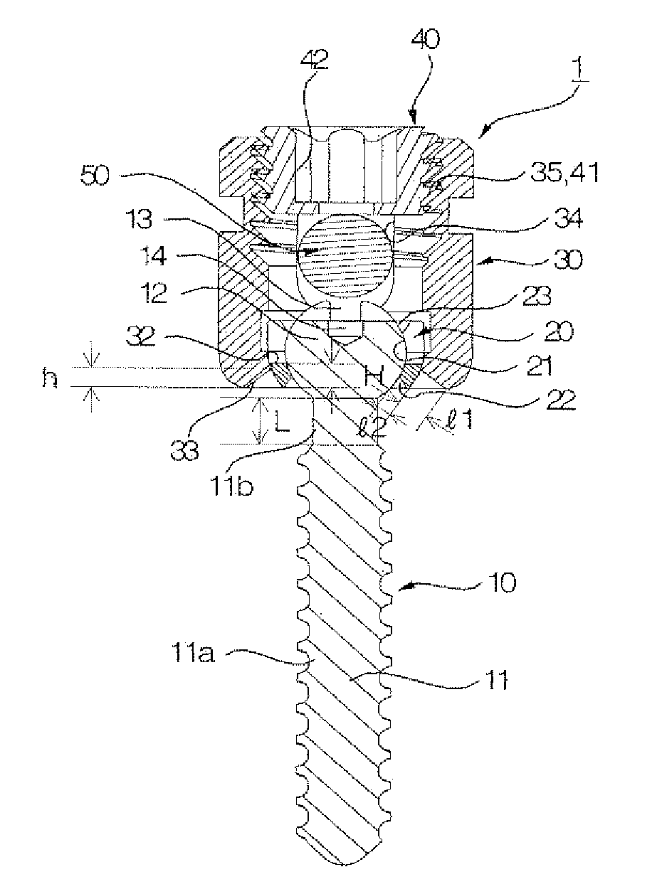
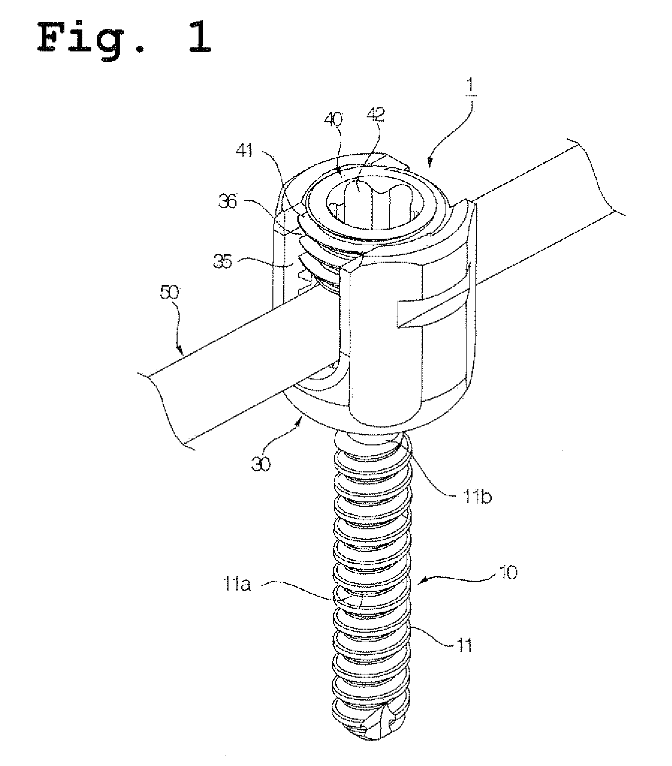
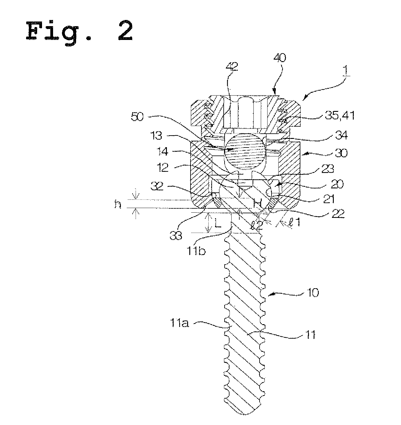
[0032]FIG. 1 is a perspective view showing a screw for fixing vertebra according to an embodiment of the present invention, and FIG. 2 is a cross sectional view of a screw for fixing vertebra shown in FIG. 1.

[0033]Referring to FIGS. 1 and 2, the screw for fixing vertebra 1 of the present embodiment includes a screw body 10, a movable washer 20 in which one end of the screw body 10 is pivotally joined, a fastening nut 30 for containing the movable washer 20 there...


PUM


Abstract

A screw for fixing vertebra for letting a patient perform spinal motion more smoothly after a pedicle screw insertion surgery is disclosed. A head portion of the screw body is pivotally joined in sliding contact on the head seat portion of a movable washer, which is also pivotally joined in sliding contact on the washer seat portion of a fastening nut. A first aperture and a second aperture are formed in the fastening nut and movable washer respectively, and an elongating portion without a thread is formed between a screw portion and the head portion of the screw body.

Description

CROSS REFERENCE TO RELATED APPLICATION[0001]This application claims priority to Korean Patent Application No. 10-2011-0126897 filed on Nov. 30, 2011 in the Korean Intellectual Property Office, the entire disclosure of which is incorporated herein by reference.BACKGROUND OF THE INVENTION[0002]1. Field of the Invention[0003]The present invention relates to a screw for fixing vertebra, and more specifically, to a screw for fixing vertebra for giving various option, for screw insertion, to an operator with maintaining condition of lower profile screw.[0004]2. Description of the Related Art[0005]In general, spinal diseases include prolapsed intervertebral disk (spinal disk) and spinal scoliosis, and a patient with part of the spine damaged cannot engage in activities necessary for daily life in such a condition. Even if the extent of damage is not so serious, if the damaged part of the spine is pressed or touched by another adjacent part it may cause pain. Due to uneven division of vario...

Claims


Application Information

Patent Timeline
Patent Type & Authority Patents(United States)
IPC IPC(8): A61B17/86A61B17/70
CPCA61B17/8605A61B17/7032A61B17/7037A61B17/70A61B17/86
Inventor KANGLEE, CHOON-SUNG
Owner L&K BIOMED CO LTD
Learn More