
Wireless communication system base station apparatus, wireless communication system terminal apparatus, wireless communication system, and method for canceling direct link mode

a wireless communication system and terminal technology, applied in the field of wireless communication system base station apparatus, wireless communication system terminal apparatus, wireless communication system, etc., can solve the problems of difficult to comfortably perform data communication in direct mode link, complicated normal data communication, etc., to achieve comfortable data communication, comfortable data communication, and convenient data communication

Inactive Publication Date: 2011-11-15
ONKYO KK D B A ONKYO CORP
View PDF3 Cites 2 Cited by
  • Summary
  • Abstract
  • Description
  • Claims
  • Application Information

AI Technical Summary

Benefits of technology

"The present invention provides a solution for cancelling the direct link mode in a wireless communication system, which allows for comfortable data communication in the direct link mode but also allows for the cancellation of the direct link mode when necessary. This is achieved through a base station apparatus that includes a specifying device for specifying an available communication band, a band information generating device for generating band information indicating the available communication band, and a cancelling device for cancelling the direct link mode by changing it to another communication mode. The cancellation instruction information is generated if a predetermined cancellation condition is satisfied on the terminal apparatus. The technical effect of the invention is to provide a base station apparatus and a terminal apparatus for wireless communication that can comfortably perform data communication in the direct link mode while also allowing for the cancellation of the direct link mode when necessary."

Problems solved by technology

Thus, particularly if the transmission target is real-time data or the like, the normal data communication becomes complicated in some cases because of the lack of communication bands accompanied with the cancellation of the direct link mode.
That is, the conventional technology has a technical problem of a difficulty in comfortably performing the data communication in the direct mode link.

Method used


Image

  • Wireless communication system base station apparatus, wireless communication system terminal apparatus, wireless communication system, and method for canceling direct link mode
  • Wireless communication system base station apparatus, wireless communication system terminal apparatus, wireless communication system, and method for canceling direct link mode
  • Wireless communication system base station apparatus, wireless communication system terminal apparatus, wireless communication system, and method for canceling direct link mode

Examples


first embodiment

Structure of Embodiment

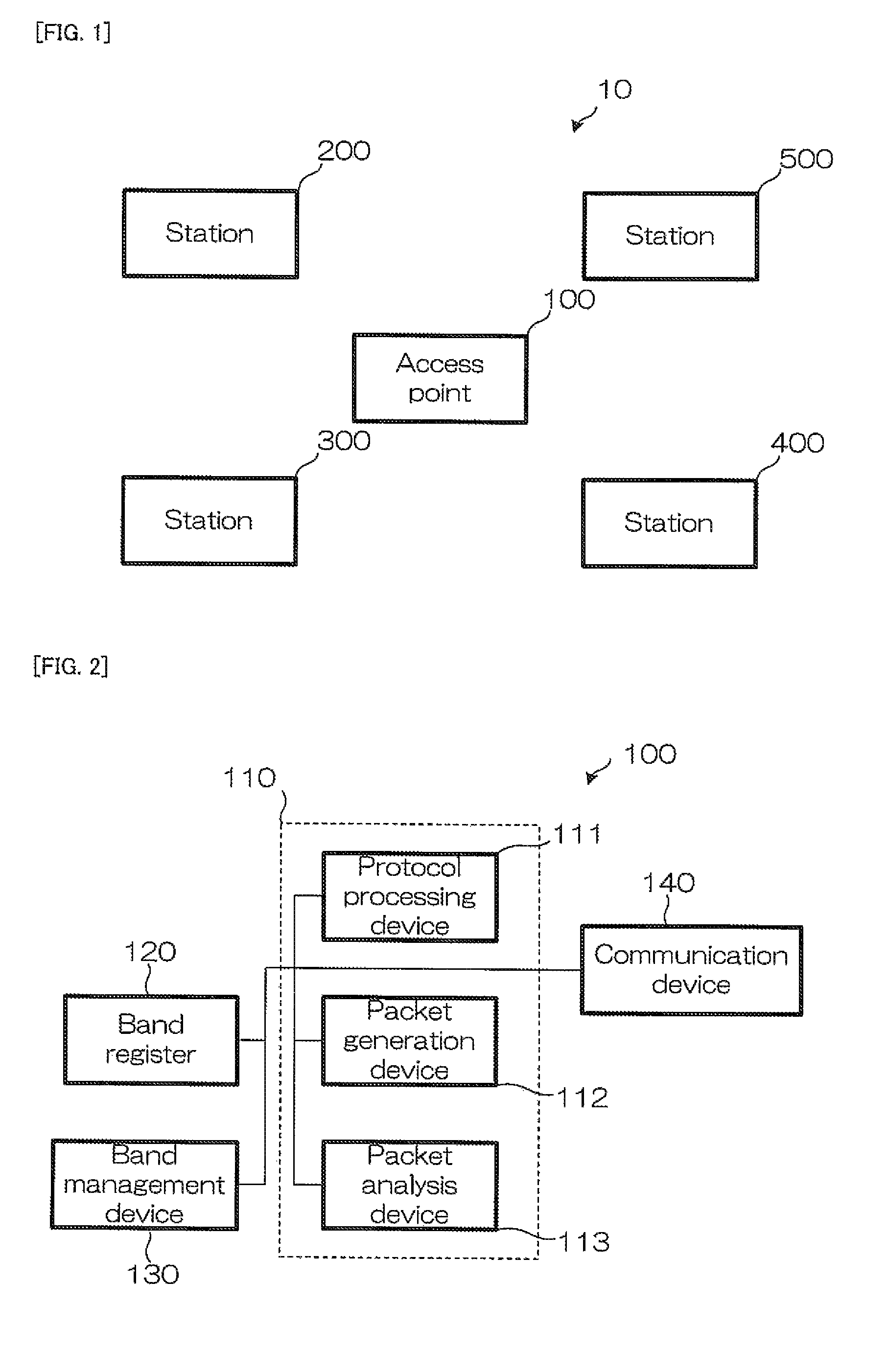
[0088]Firstly, with reference to FIG. 1, the structure of a wireless communication system in a first embodiment of the present invention will be explained. FIG. 1 is a conceptual view showing a wireless communication system 10.

[0089]In FIG. 1, the wireless communication system 10 is a wireless LAN system complying with the IEEE 802.11e standard. The wireless communication system 10 is provided with: an access point 100; a station 200; a station 300; a station 400; and a station 500, and it is one example of the “wireless communication system” of the present invention. In the wireless communication system10, each station is set within a communication range of the access point 100.

[0090]Next, with reference to FIG. 2, the detailed structure of the access point 100 will be explained. FIG. 2 is a block diagram showing the access point 100. Incidentally, in FIG. 2, the same points as those in FIG. 1 carry the same numerical references and the explanation thereof wi...

embodiment

Operation of Embodiment

[0106]

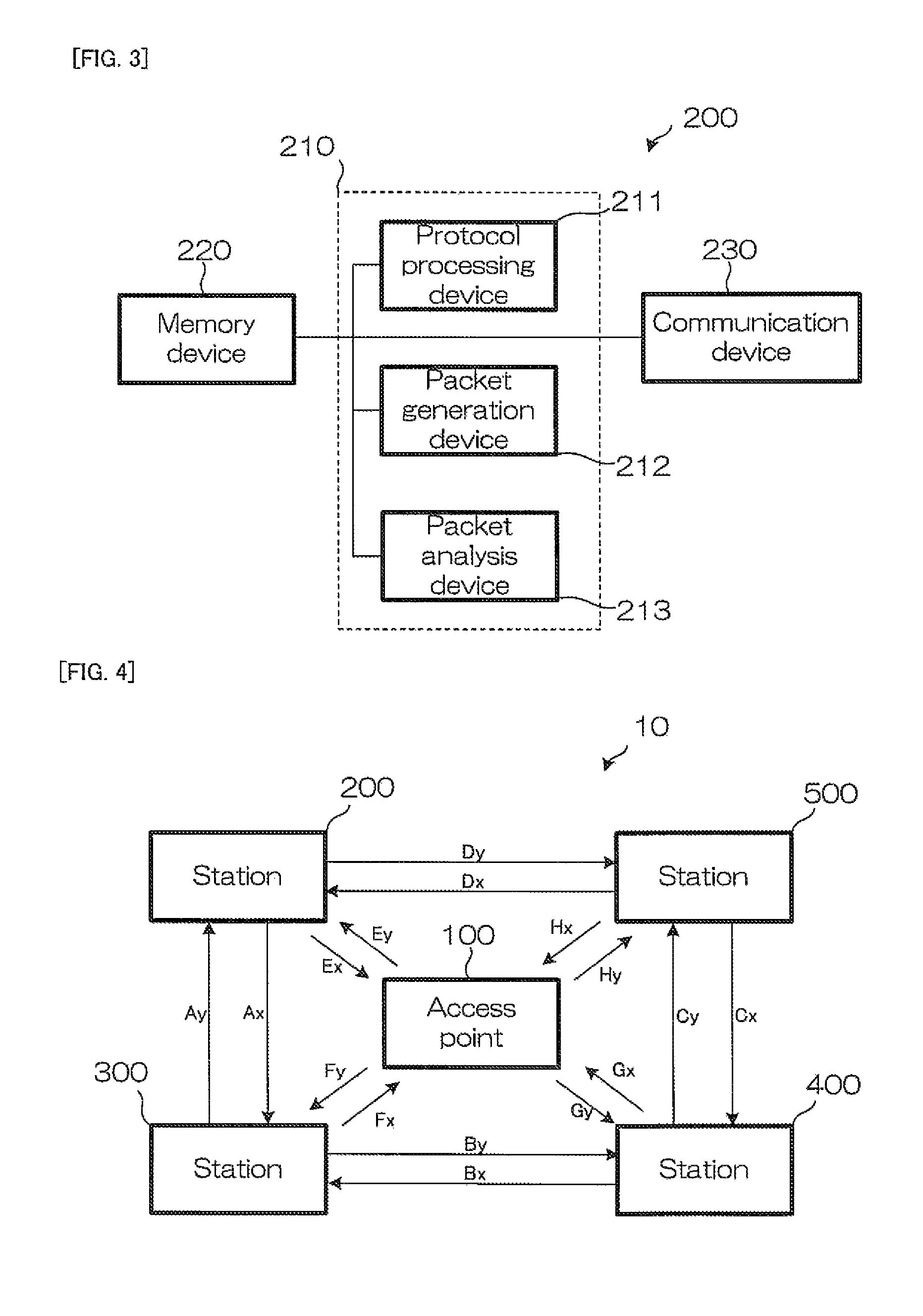
[0107]Next with reference to FIG. 4, the overview of the operation of the wireless communication system 10 will be explained. FIG. 4 is a schematic diagram showing a data flow in the wireless communication system in FIG. 1. Incidentally, in FIG. 4, the same points as those in FIG. 1 carry the same numerical references and the explanation thereof will be omitted.

[0108]In FIG. 4, the wireless communication system 10 is adapted for the data communication between the stations. The wireless communication system 10 is provided with two types of communication modes, i.e. a normal mode and a direct link mode, as the communication mode of the data communication.

[0109]The normal mode is a communication mode in which the data communication is performed through the access point 100 between the stations. That is, in this case, it can cause a data flow directed to the access point 100 from each station (refer to illustrated arrows Ex, Fx, Gx, and Hx) and a data flow d...

second embodiment

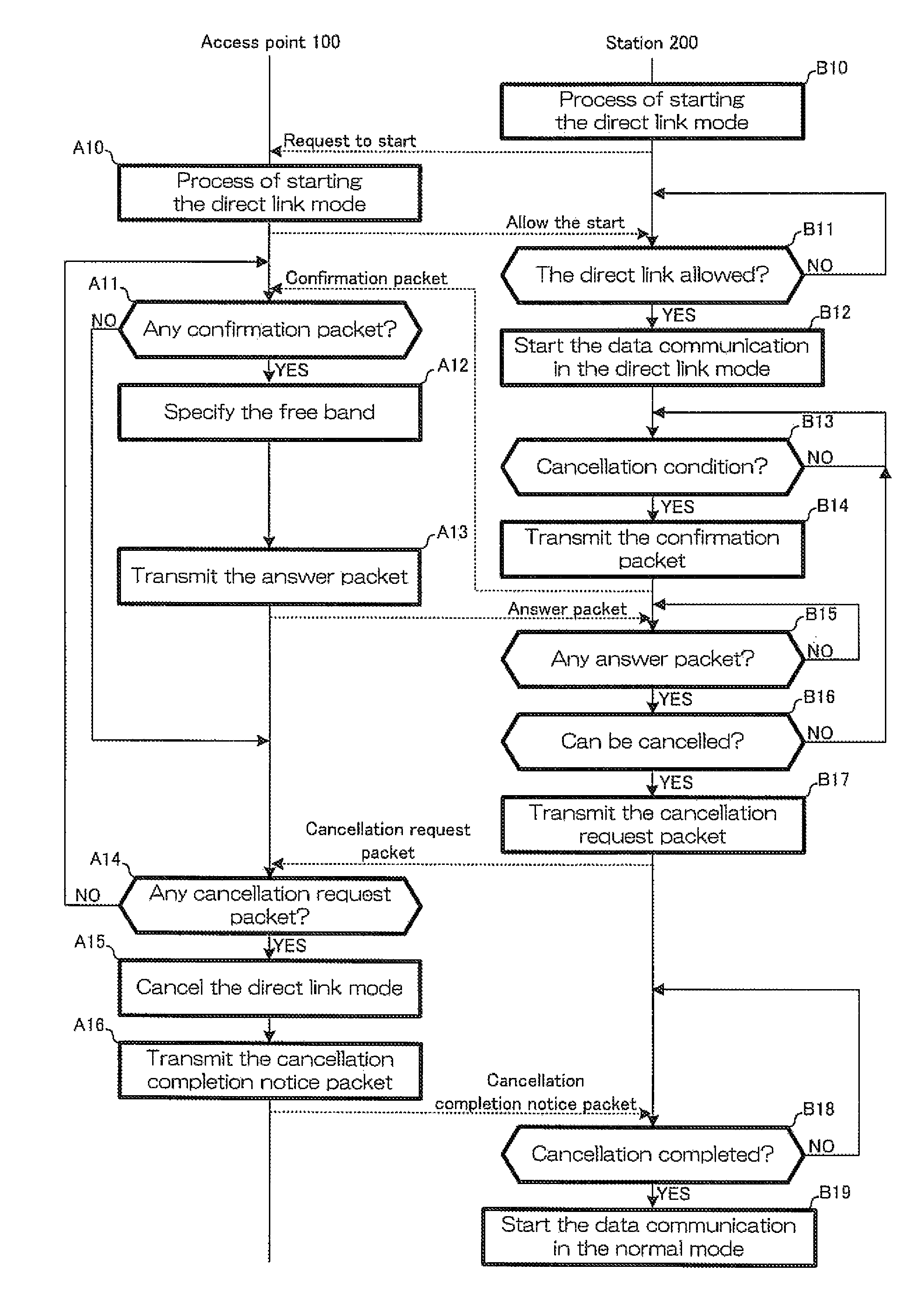
[0136]In the first embodiment, the free band is confirmed if the direct link mode is to be cancelled however, the direct link mode can be preferably cancelled in another method by specifying the free band in the access point 100. Now, with reference to FIG. 6, an explanation is given on another method of cancelling the direct link mode, as a second embodiment of the present invention. FIG. 6 is another timing chart showing a flow of operations from the start to the end of the direct link mode, with regard to the access point 100 and the station 200. Incidentally, in FIG. 6, the same points as those in FIG. 5 carry the same numerical references and the explanation thereof will be omitted.

[0137]In FIG. 6, in the station 200, a reservation packet (i.e. one example of the “reservation request information” of the present invention) indicating to request the reservation of the communication band, required to change the direct link mode between the station 200 and the station 300 to the no...


PUM


Abstract

In a wireless communication system (10), when a direct link mode is to be canceled, a station (200) generates a confirmation packet for confirming an unused band of the wireless communication system (10) and transmits the confirmation packet to an access point (100). At the access point (100), a band management part (130) determines the unused band, and a packet generating part (112) generates a response packet indicative of the unused band, which is then transmitted to the station (200). The station (200) determines, based on the unused band indicated by the response packet, whether the direct link mode should be canceled, and transmits a cancellation request packet to the access point (100) if the unused band is sufficient. At the access point (100), the direct link mode is switched to a normal mode for cancellation in response to the cancellation request packet.

Description

TECHNICAL FIELD[0001]The present invention relates to a base-station apparatus for a wireless communication system, a terminal apparatus for a wireless communication system, a wireless communication system, and a method of canceling a direct link mode, which is preferably used for those apparatuses and system.BACKGROUND ART[0002]As this type of wireless communication system, there is suggested a wireless LAN provided with a direct link mode (e.g. refer to a non-patent document 1).[0003]According to the wireless LAN disclosed in the non-patent document 1 (hereinafter referred to a “conventional technology”), it allows preferable transmission of real-time data or the like, compared to data communication via an access point, by providing the direct link mode for direct data communication between a plurality of stations participating a network.[0004]Non-patent document 1: Shiro SAKATA, “Ubiquitous Technology Wireless Communication LAN”, Jun. 25, 2004, p. 165-166DISCLOSURE OF INVENTIONSu...

Claims


Application Information

Patent Timeline
Patent Type & Authority Patents(United States)
IPC IPC(8): H04M1/00H04B1/38H04W48/08H04W72/04H04W76/06H04W84/12H04W84/18H04W88/08H04W92/10
CPCH04W76/043H04W76/06H04W88/08H04W92/18H04W76/23H04W76/30
Inventor MATSUMARU, MAKOTO
Owner ONKYO KK D B A ONKYO CORP
Learn More