Device for equalizing the back foci of objective and camera

Inactive Publication Date: 2007-06-26
CARL ZEISS SMT GMBH
View PDF6 Cites 3 Cited by
  • Summary
  • Abstract
  • Description
  • Claims
  • Application Information

AI Technical Summary

Benefits of technology

[0010]By the measure of providing a device by means of which a graphic pattern is provided at a predetermined distance, it is possible to be able to comfortably perform the equalization of the back foci by making use of this graphic pattern.
[0012]A device, preferably a clamping device, has furthermore been found to be advantageous for fastening the device to the objective, so that no separate holder is required for the device.
[0015]An advantageous development of the device is to construct the device in modules, so that the ability of the device to function can be quickly restored by changing individual modules when there is a defect. Furthermore, by interchanging individual modules it is possible to change the properties of the device. Thus, for example, the distance at which the graphic pattern is imaged, or the graphic pattern itself, can be changed.

Problems solved by technology

Moreover, the objective holder in the camera is as a rule made of aluminum, and greater wear can be expected.
The adjustment to the correct back focus must take place very accurately, since a faulty setting results in out of focus pictures.

Method used


Image

  • Device for equalizing the back foci of objective and camera
  • Device for equalizing the back foci of objective and camera
  • Device for equalizing the back foci of objective and camera

Examples


Embodiment Construction

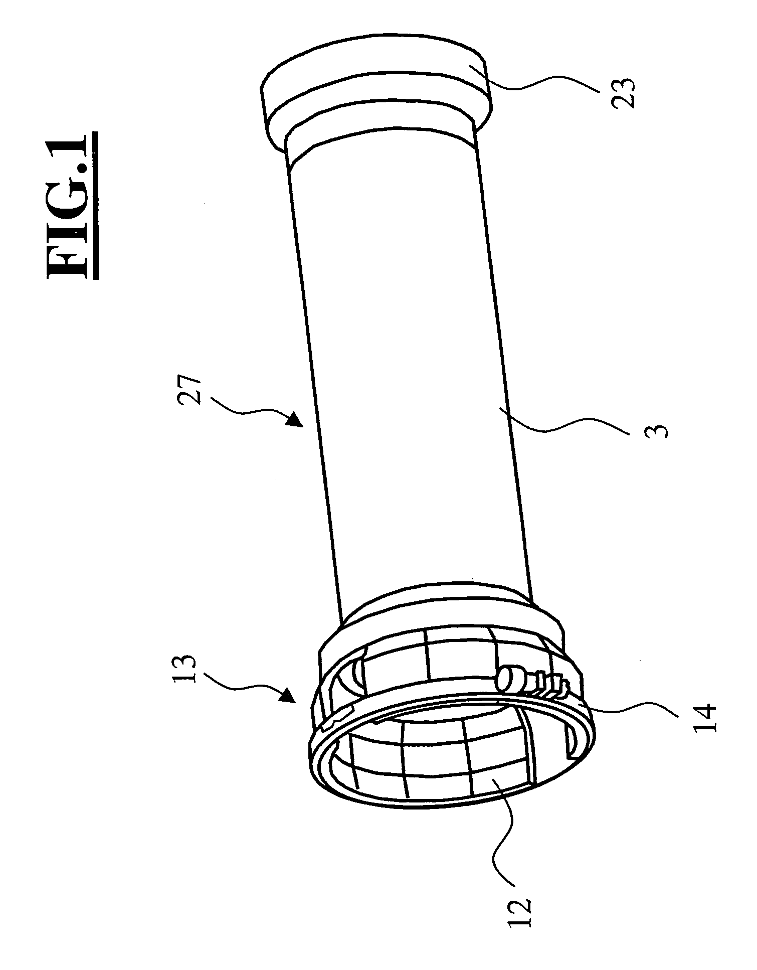
[0021]FIG. 1 shows an external view of a device according to the invention. The device 1 includes a clamping device 13 with a tightening ring 14 which coaxially surrounds clamp jaws 12. This clamping device represents one of the modules included in the device. The device can be frictionally connected to the objective of a camera by means of the clamping device. Alternatively, a positive connection such as screws or a latch connection can be provided.

[0022]Further modules, which can be seen in FIG. 1, are the image module 23 and the middle module 27 with the housing 3.

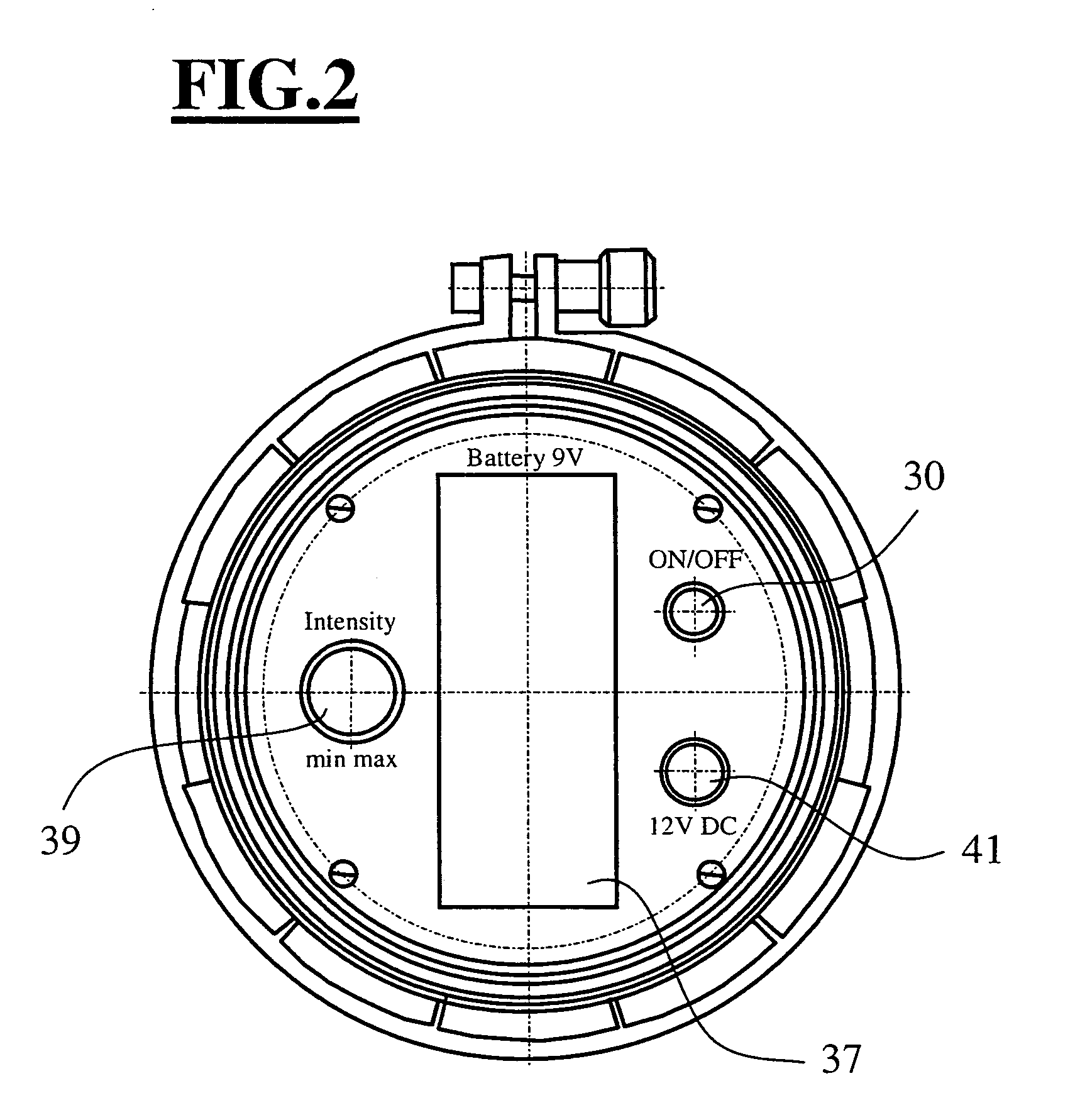
[0023]FIG. 2 shows a plan view of the end situated opposite to the clamping device.

[0024]Arranged at this end are a on / off switch 30, a plug connection 41 for an external current supply, and a brightness control 39 for an illumination arrangement provided within the device, and the battery compartment 37. The current supply can also be used for charging the battery.

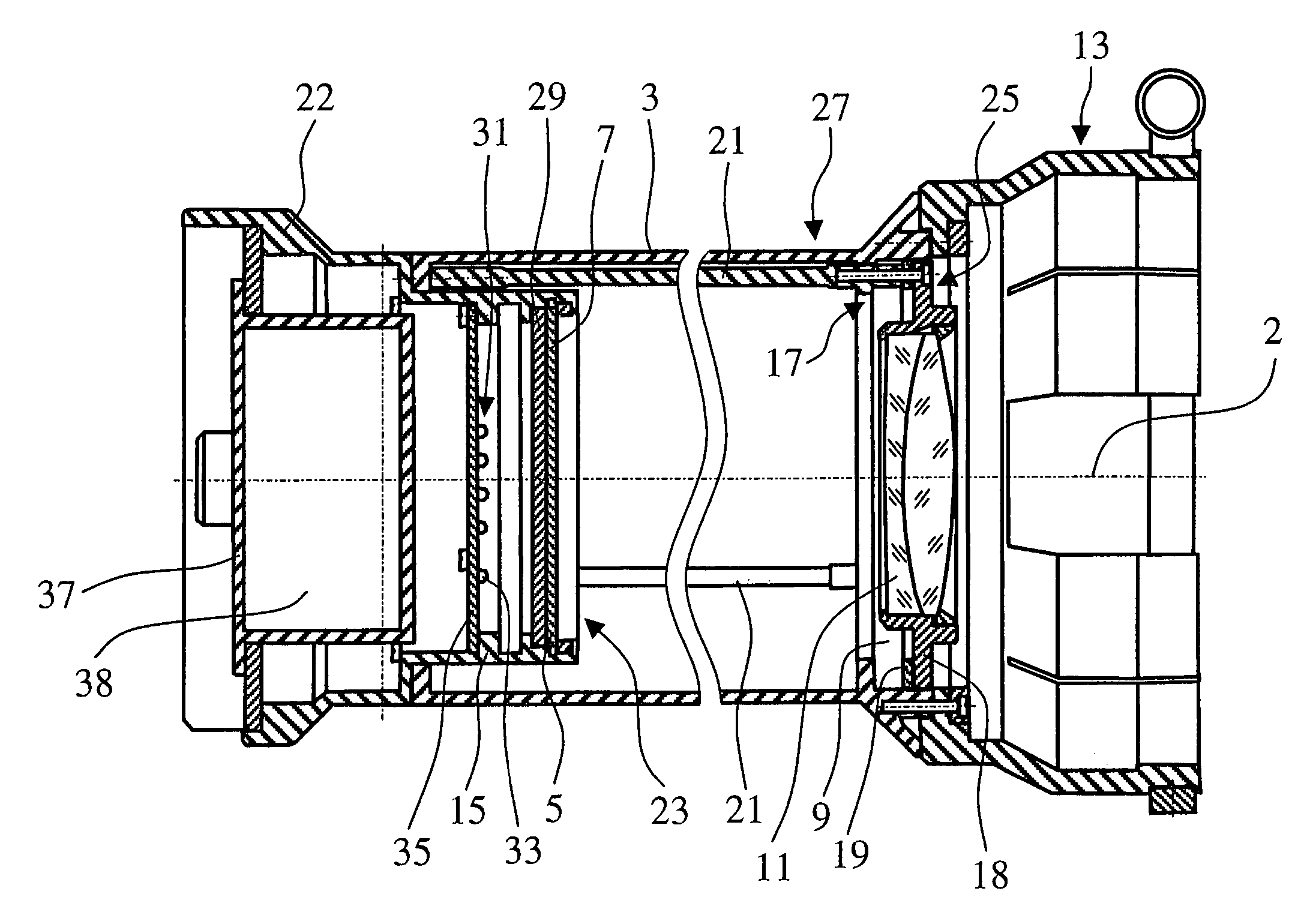
[0025]FIG. 3 shows a section through the device 1 along...


PUM


Abstract

A device for adjusting the back foci of an objective and a camera to one another has a housing by which a graphic pattern and an optics are mounted at a predetermined distance F′ from each other. The temperature compensation for the distance F′ is constant to ±2 mm for a temperature change of Delta 20° Celsius. The device also includes an apparatus for matching the back foci of an objective and a camera to each other, in which a housing has a fastening mechanism for fastening an object-side end of the objective and a graphic pattern is arranged in the housing on the end of the device opposite the fastening mechanism. The invention also includes a method for equalizing the back foci of an objective and camera using specific steps.

Description

CROSS-REFERENCES TO RELATED APPLICATIONS[0001]Not applicable.STATEMENT REGARDING FEDERALLY SPONSORED RESEARCH OR DEVELOPMENT[0002]Not applicable.BACKGROUND OF THE INVENTION[0003]A new series of objectives under the name “Digiprime” has been offered by the Zeiss company. The objectives are for high definition digital cameras. Such cameras are offered, for example, by the Sony or Panasonic companies.[0004]An essential difference from the objectives for film cameras heretofore consists of the possibility of changing the image-side intercept distance (termed “back focus” in English) of the objective by means of a rotary ring. This is necessary because the tolerance for the back focus within the camera is large in comparison with a film camera. Moreover, the objective holder in the camera is as a rule made of aluminum, and greater wear can be expected. Such an adjustment can of course be achieved in that the back focus of the camera is changed, or a back focus change takes place by means...

Claims


Application Information

Patent Timeline
IPC IPC(8): G02B15/14G02B7/02G02B27/40G02B27/62H04N5/225H04N5/232
CPCG02B7/028G02B27/40G02B27/62H04N5/2254H04N5/23212H04N23/55H04N23/67
Inventor WEBER, UWEMULLER, GEBHARD
Owner CARL ZEISS SMT GMBH
Why Eureka
Try Eureka