Front cowl structure for saddle riding type vehicle

a technology of front cowl and saddle, which is applied in the direction of combustion air/fuel air treatment, cycle equipment, optical signal, etc., can solve the problems of airflow blowing against a rider, structure is not properly designed to make the most of air pressure, and the airflow is thus slightly bent, so as to achieve effective air drawing, effective air drawing, and ram pressure

Active Publication Date: 2015-09-01
HONDA MOTOR CO LTD
View PDF5 Cites 0 Cited by
  • Summary
  • Abstract
  • Description
  • Claims
  • Application Information

AI Technical Summary

Benefits of technology

[0016]According to an embodiment of the present invention, the duct opening that opens forwardly of the vehicle is formed to be substantially aligned in the vehicle longitudinal direction with the cowl opening central portion of the cowl front surface opening that opens the cowl front surface at the leading end portion of the front cowl. A stream of air entering the duct opening while the vehicle is being operated can have part of the flow at the highest speed disposed at the central portion of the duct opening without being affected by the vehicle body shape, so that ram pressure of the stream of air flowing in the duct can be maximized to thereby achieve an effective drawing of air. In addition, the headlights disposed on both lateral sides of the cowl front surface opening each has a lens surface, the lens surface forming an opening edge portion on a corresponding lateral side of the cowl front surface opening and being inclined to the vehicle outer side and rearwardly from the opening edge portion. No step is thus formed of a connection between the headlight on either lateral side of the cowl front surface opening and the front cowl. Turbulence in the airflow does not therefore occur at the opening edge portions and the airflow that flows into the duct can be drawn as a laminar flow.
[0017]According to an embodiment of the present invention, the cowl front surface opening is formed such that all opening edge portions of the duct opening are visible as viewed from the vehicle forward side. No obstacles are formed that block inflow of air exist in an area forward of the duct opening. Thus, a smooth inflow of air and effective drawing of air is provided.
[0018]According to an embodiment of the present invention, the cowl front surface opening has a shouldered portion such that the entrance side wall of the opening entrance portion on the vehicle forward side has an opening width that is narrower than an opening width of the communicating path side wall of the communicating path that communicates with the duct opening. The shouldered portion can separate the stream of air flowing into the cowl front surface opening from the communicating path side wall, thus avoiding sticking of the stream of air onto the communicating path side wall. Thus, vehicle turning performance can thereby be improved.
[0019]According to an embodiment of the present invention, the cowl front surface opening is formed substantially into an M-shape including the pairs of left and right taper edge portions that extend to taper toward the rear of the front cowl. Thus, the boundary line portion between the cowl upper surface center portion and the cowl upper surface side portion on either lateral side of the front cowl is formed to be joined to the taper edge portions. A stream of air flowing from the opening edge portion of the cowl front surface opening to a cowl outer surface can thus be guided along the taper edge portions to flow along the cowl outer surface profile. This creates a stream of air flowing along the profile of the upper surface of the front cowl to thereby contain turbulence in the stream of air. Thus, a smooth airflow flowing over the upper surface of the front cowl is provided. As a result, the airflow flowing over the upper surface of the front cowl is smooth to provide a gentle airflow that blows against the rider.
[0020]According to an embodiment of the present invention, the boundary line portion between the cowl upper surface center portion and the cowl upper surface side portion is formed into a recess that extends from the merging vertex of the taper edge portions rearwardly of the front cowl. A turbulent flow produced at the opening edge portion of the cowl front surface opening can thus be made to flow from the merging vertex of the taper edge portions through the inside of the boundary line portion having a recessed shape to the rear of the front cowl. A laminar flow portion and a turbulent flow portion on both lateral sides of the cowl can thereby be properly isolated from each other, so that an adverse effect from the turbulent flow on the laminar flow can be minimized and the laminar flow can be maintained to minimize operating resistance.
[0021]According to an embodiment of the present invention, the lens surface is inclined such that the entire surface thereof faces downwardly and rearwardly of the vehicle. Even when the lens surface is made large, the foregoing aspect of the present invention allows a lens area to be held small and a front cowl area to be large when viewed from the front side. Airflow smoothing action by the front cowl can therefore be improved.

Problems solved by technology

The airflow supplied to the duct portion is thus slightly bent and the structure is not properly designed to make the most of air pressure of the airflow.
In the structure having the air introducing opening forwardly of the front cowl, as in Japanese Patent Laid-Open No. 2010-149806, turbulence is more likely to occur in a stream of air flowing over a front cowl surface, causing the airflow blowing against a rider to be disrupted, thus degrading ride comfort.

Method used


Image

  • Front cowl structure for saddle riding type vehicle
  • Front cowl structure for saddle riding type vehicle
  • Front cowl structure for saddle riding type vehicle

Examples


Embodiment Construction

[0032]A specific embodiment to which the present invention is applied will be described below.

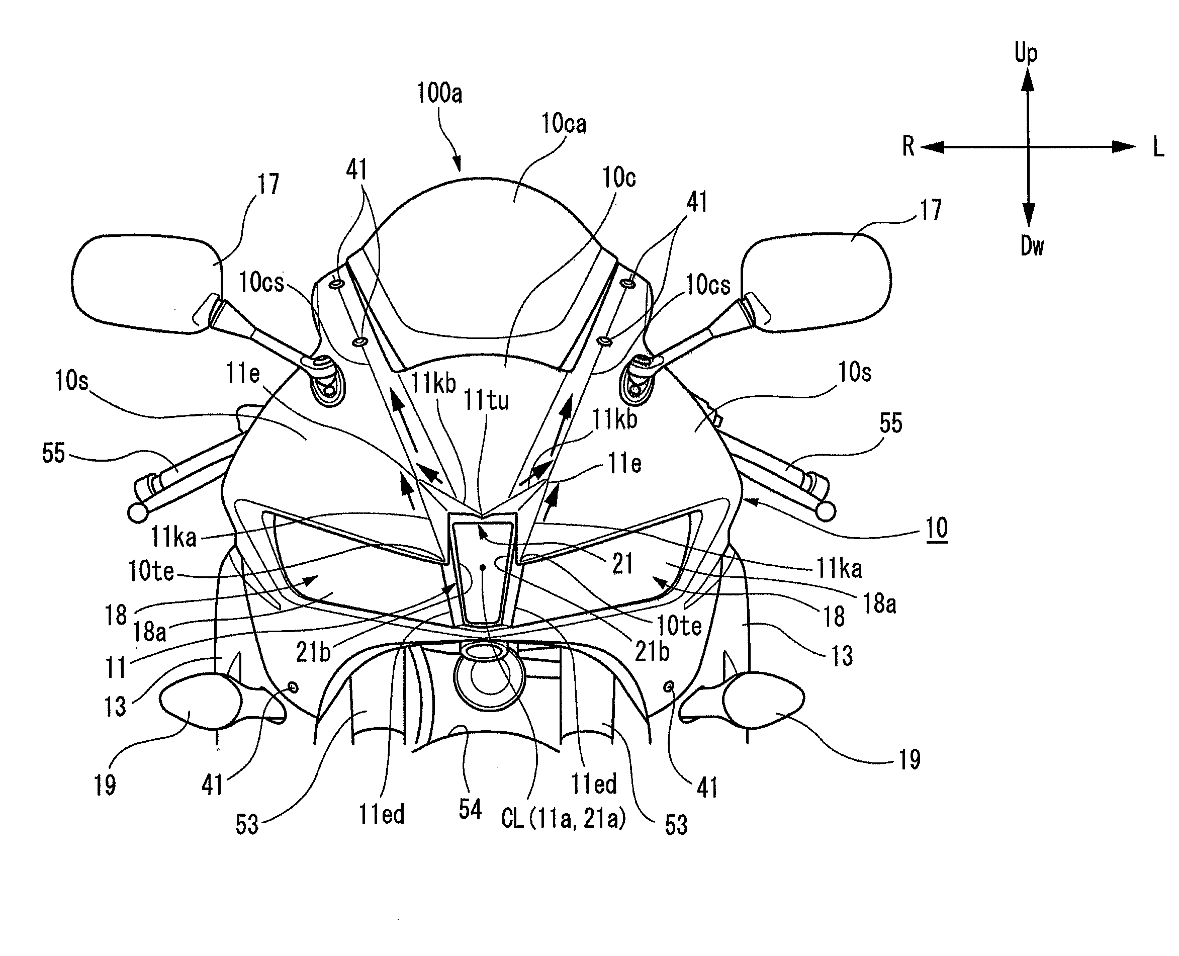
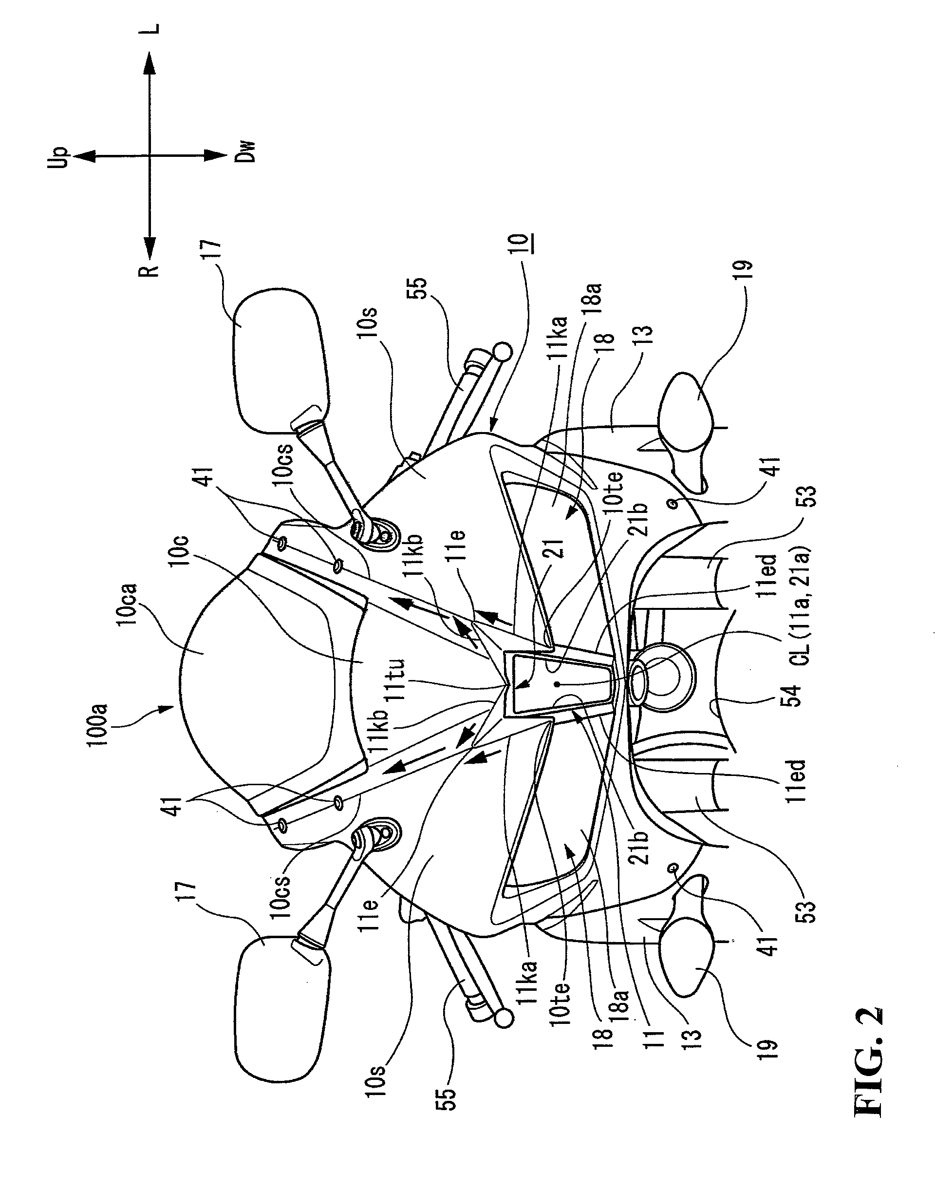
[0033]A saddle riding type vehicle, such as a motorcycle, according to an embodiment of the present invention will be described in detail below with reference to FIGS. 1 to 8.

[0034]The drawings should be viewed in the direction of the reference numerals. The drawings show arrows to indicate directions relative to an operating direction of the motorcycle, an arrow Fr denoting a vehicle forward direction, an arrow Rr denoting a vehicle rearward direction, an arrow Up denoting a vehicle upward direction, and an arrow Dw denoting a vehicle downward direction, respectively.

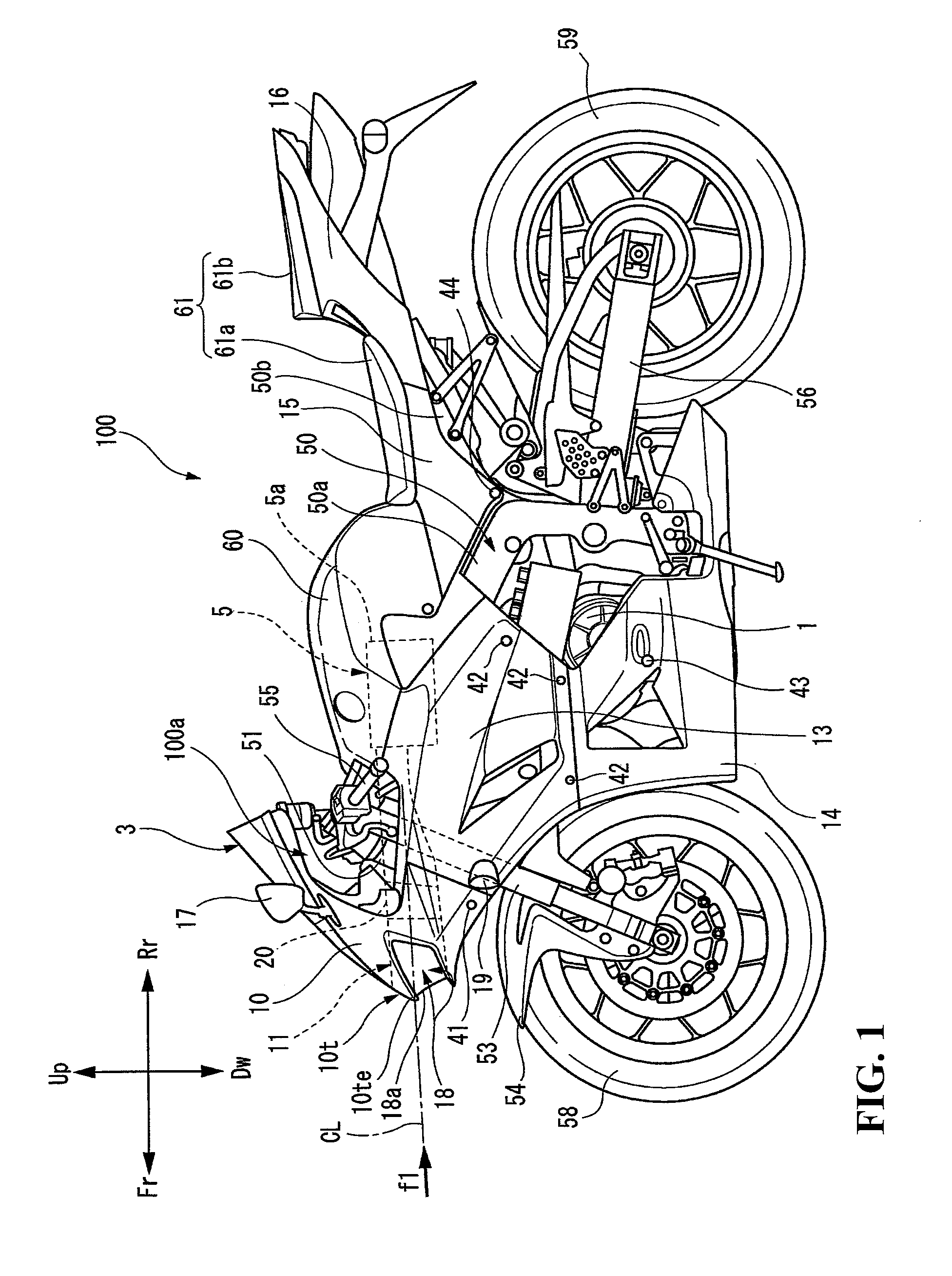
[0035]FIG. 1 is a side elevational view showing a motorcycle 100 according to an embodiment of the present invention.

[0036]The motorcycle 100 includes a vehicle body frame 50 having a framework on which various component parts are attached. The vehicle body frame 50 includes a head pipe 51 disposed at a vehicle front end porti...


PUM


Abstract

A front cowl structure for a saddle riding type vehicle for preventing turbulence in a stream of air flowing over a front cowl surface. The front cowl structure includes a duct placed inside a front cowl with a duct opening that opens to the front of the vehicle. The front cowl has a cowl front surface opening at a leading end portion thereof for opening a cowl front surface. Headlights are disposed on both lateral sides of the cowl front surface opening with each having a lens surface. The lens surfaces form opening edge portions on both lateral sides of the cowl front surface opening. The lens surfaces are each inclined to a vehicle outer side and rearwardly from the opening edge portions. The duct opening and a cowl opening central portion of the cowl front surface opening are substantially aligned with each other in a vehicle longitudinal direction.

Description

CROSS-REFERENCE TO RELATED APPLICATIONS[0001]The present application claims priority under 35 USC 119 to Japanese Patent Application No. 2012-217663 filed Sep. 28, 2012 the entire contents of which are hereby incorporated by reference.BACKGROUND OF THE INVENTION[0002]1. Field of the Invention[0003]The present invention relates generally to front cowl structures for saddle riding type vehicles. More specifically, to a front cowl structure for a saddle riding type vehicle including a front cowl having an intake opening.[0004]2. Description of Background Art[0005]A saddle riding type vehicle is disclosed, for example, in Japanese Patent Laid-Open No. 2010-149806. This saddle riding type vehicle includes a duct portion of an air cleaner, the duct portion opening forwardly in the vehicle with an air introducing opening formed forwardly of a front cowl corresponding to the open duct portion. This arrangement is designed to supply an airflow from the vehicle forward direction to an intake ...

Claims


Application Information

Patent Timeline
Patent Type & Authority Patents(United States)
IPC IPC(8): B62J17/02B62J6/02F02M35/16F02M35/10
CPCB62J17/02B62J6/02F02M35/10013F02M35/162B62J6/026
Inventor MAEDA, RUIKOROGI, YOSHINORIYUKI, SHINSUKETAKASAKI, ATSUSHIYOKOKAWA, SHUNJI
Owner HONDA MOTOR CO LTD
Why Eureka
Try Eureka