
Tire uniformity through identification of process signatures

a process signature and uniformity technology, applied in the field of tires, can solve the problems of tire non-uniformity, tire non-uniformity is important, and the non-uniformity present in the tire structure produces periodic varying forces, so as to improve the uniformity, reduce the combined average magnitude of tire and process effects, and optimize the angular location of components contributing to tire harmonies

Active Publication Date: 2015-09-01
MICHELIN & CO CIE GEN DES ESTAB MICHELIN
View PDF19 Cites 4 Cited by
  • Summary
  • Abstract
  • Description
  • Claims
  • Application Information

AI Technical Summary

Benefits of technology

This approach effectively reduces the combined average magnitude of tire and process effects, enhancing ride comfort by filtering out process harmonics and optimizing tire component placement, leading to improved uniformity and reduced manufacturing dispersion.

Problems solved by technology

Conventional tire building methods unfortunately have many opportunities for producing non-uniformities in tires.
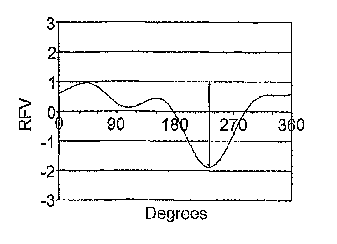
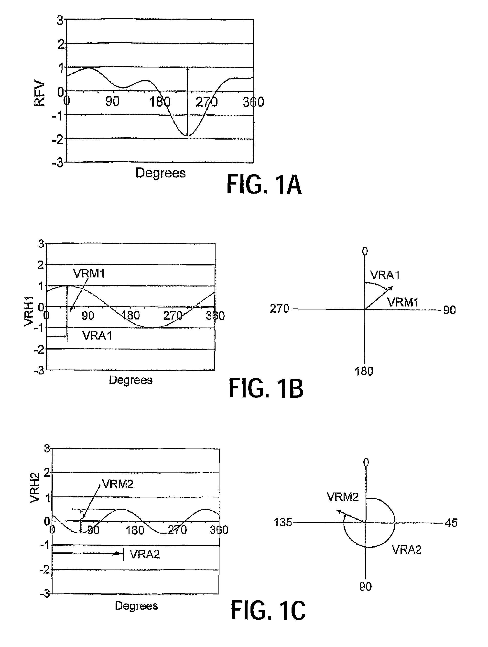
During rotation of the tires, non-uniformities present in the tire structure produce periodically-varying forces at the wheel axis.
Tire non-uniformities are important when these force variations are transmitted as noticeable vibrations to the vehicle and vehicle occupants.
However, this type of uniformity analysis may be hindered by the impact of process effects whose periodic contributions to the composite uniformity waveform are not identical to the tire harmonics, resulting in poorer compensations and adjustments.
Although known technologies for tire uniformity improvement have been developed, no design has emerged that generally encompasses all of the desired characteristics as hereafter presented in accordance with the subject technology.

Method used


Image

  • Tire uniformity through identification of process signatures
  • Tire uniformity through identification of process signatures
  • Tire uniformity through identification of process signatures

Examples


example

[0081]To better appreciate the process illustrated in FIG. 6 and described above, a numerical example of process effect evaluation is presented based on simulated results. The results below provide simulated data (i.e., test results for hypothetical tires), but exemplify the types of improvements in uniformity achieved from applying the subject analysis to actual manufactured tires. Table 1 below provides a set of simulated uniformity waveform data where radial force (VR) is measured for n=5 tires having some known manufacturing order. For simplicity, the number of data points measured in step 602 around the circumference of each tire is x=4.

[0082]A candidate process effect is identified in step 606 as an out-of-round roller with a circumference that is 1.25 times the circumference of the tire on which it is being used. Steps 602 and 604 involve collecting the measurement data and stringing it together into one long waveform plotted using the data in Table 1.

[0083]

TABLE 1Simulated M...


PUM

PropertyMeasurementUnit
lengthaaaaaaaaaa
lengthaaaaaaaaaa
frequencyaaaaaaaaaa

Abstract

A system and related method for improving tire uniformity includes providing a number (n) of test tires manufactured in a known order and identifying at least one candidate cyclic process effect with a corresponding frequency of introduction (f). A given uniformity parameter, such as radial or lateral run-out, balance, mass variation, radial lateral or tangential force variation, is measured for each tire in the test set, and measured data points are combined into a concatenated composite waveform. At least one process harmonic associated with each identified cyclic process effect is separated from the tire harmonics, for example, by Fourier transformation with identification of the process harmonics as positive integer multiples of the mth harmonic of the measured uniformity parameter where m=n / f. Once the process harmonics are extracted, filtered uniformity measurements can be provided or new tires can be built with the process effect minimized.

Description

PRIORITY STATEMENT[0001]The present application is a 371 of PCT / US2010 / 328823 filed Apr. 29, 2010 which claims the benefit of priority of PCT / US2009 / 042350 filed Apr. 30, 2009.FIELD OF THE INVENTION[0002]The invention relates to tire uniformity, and more specifically to a method for analyzing and controlling the uniformity of tires during and after tire manufacturing.BACKGROUND OF THE INVENTION[0003]Tire non-uniformity relates to the symmetry (or lack of symmetry) relative to the tire's axis of rotation in mass, geometric or stiffness characteristics. Conventional tire building methods unfortunately have many opportunities for producing non-uniformities in tires. During rotation of the tires, non-uniformities present in the tire structure produce periodically-varying forces at the wheel axis. Tire non-uniformities are important when these force variations are transmitted as noticeable vibrations to the vehicle and vehicle occupants. These forces are transmitted through the suspensio...

Claims


Application Information

Patent Timeline
Patent Type & Authority Patents(United States)
IPC IPC(8): G06F19/00B29D30/06
CPCB29D30/0633B29D2030/0635G01M17/02
Inventor MAWBY, WILLIAM DAVIDJETER, JIMMY
Owner MICHELIN & CO CIE GEN DES ESTAB MICHELIN
Learn More