
Method and apparatus for configuring a frequency dependent I/Q imbalance compensation filter

a filter technology, applied in electrical equipment, transmission monitoring, digital transmission, etc., can solve the problems of significant frequency dependent i/q imbalance, performance loss, and degrade the image rejection ratio (irr) of the receiver, and achieve the effect of significantly reducing the computational complexity of obtaining such estimate filtering values

Inactive Publication Date: 2015-08-25
MEDIATEK SINGAPORE PTE LTD SINGAPORE
View PDF2 Cites 1 Cited by
  • Summary
  • Abstract
  • Description
  • Claims
  • Application Information

AI Technical Summary

Benefits of technology

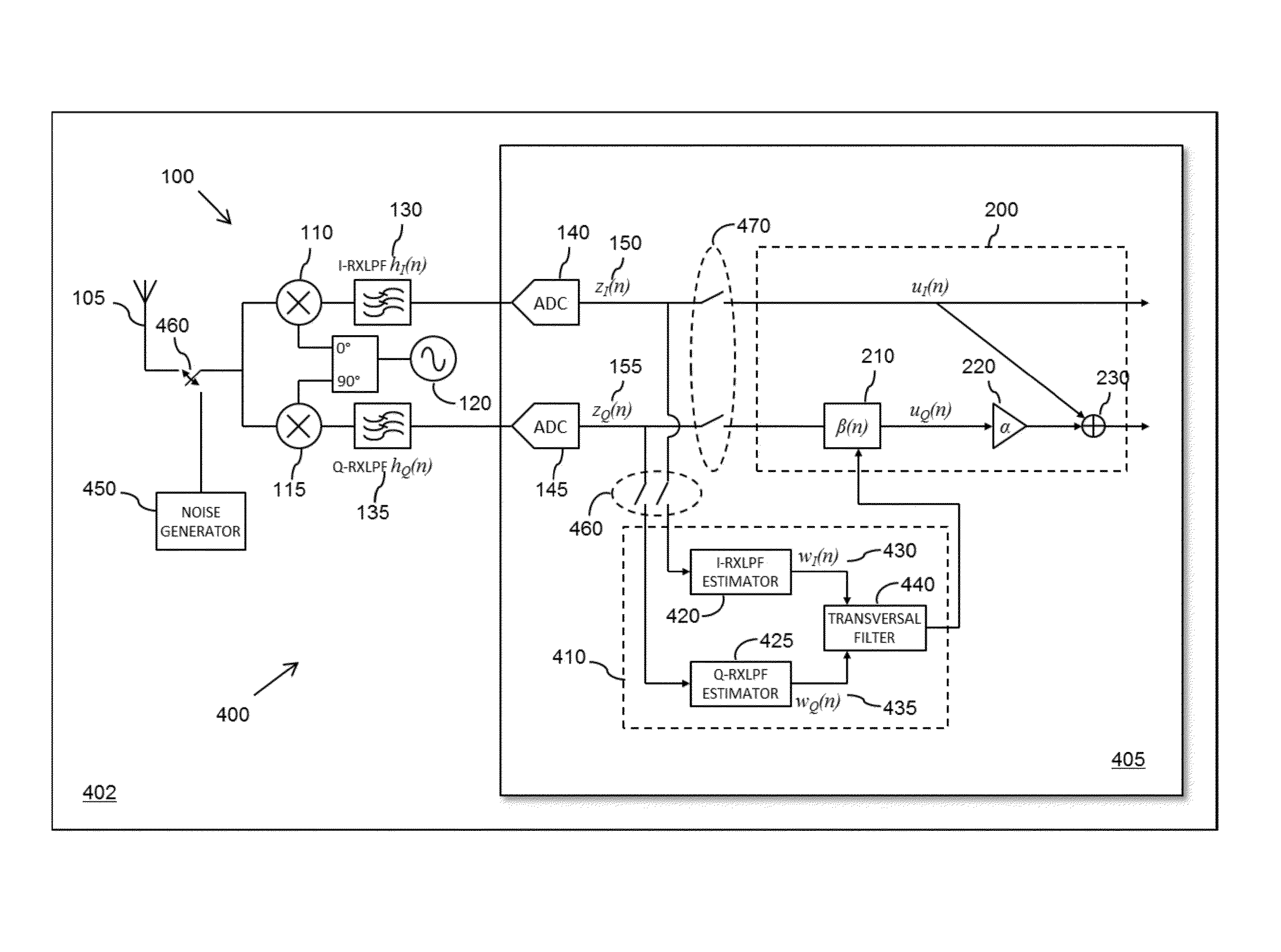
[0023]In this manner, by using a ratio between I-path and Q-path filtering estimate values to configure the coefficient(s) for the FD I / Q imbalance compensation filter, it is not necessary to accurately derive the complete filtering performed on each of the ‘I’ and ‘Q’ paths within the RF module. It is sufficient to only estimate filtering values that are representative of the difference between ‘I’ and ‘Q’ path filtering. As such, the computational complexity of obtaining such estimate filtering values may be significantly reduced as compared with conventional blind algorithm techniques.

Problems solved by technology

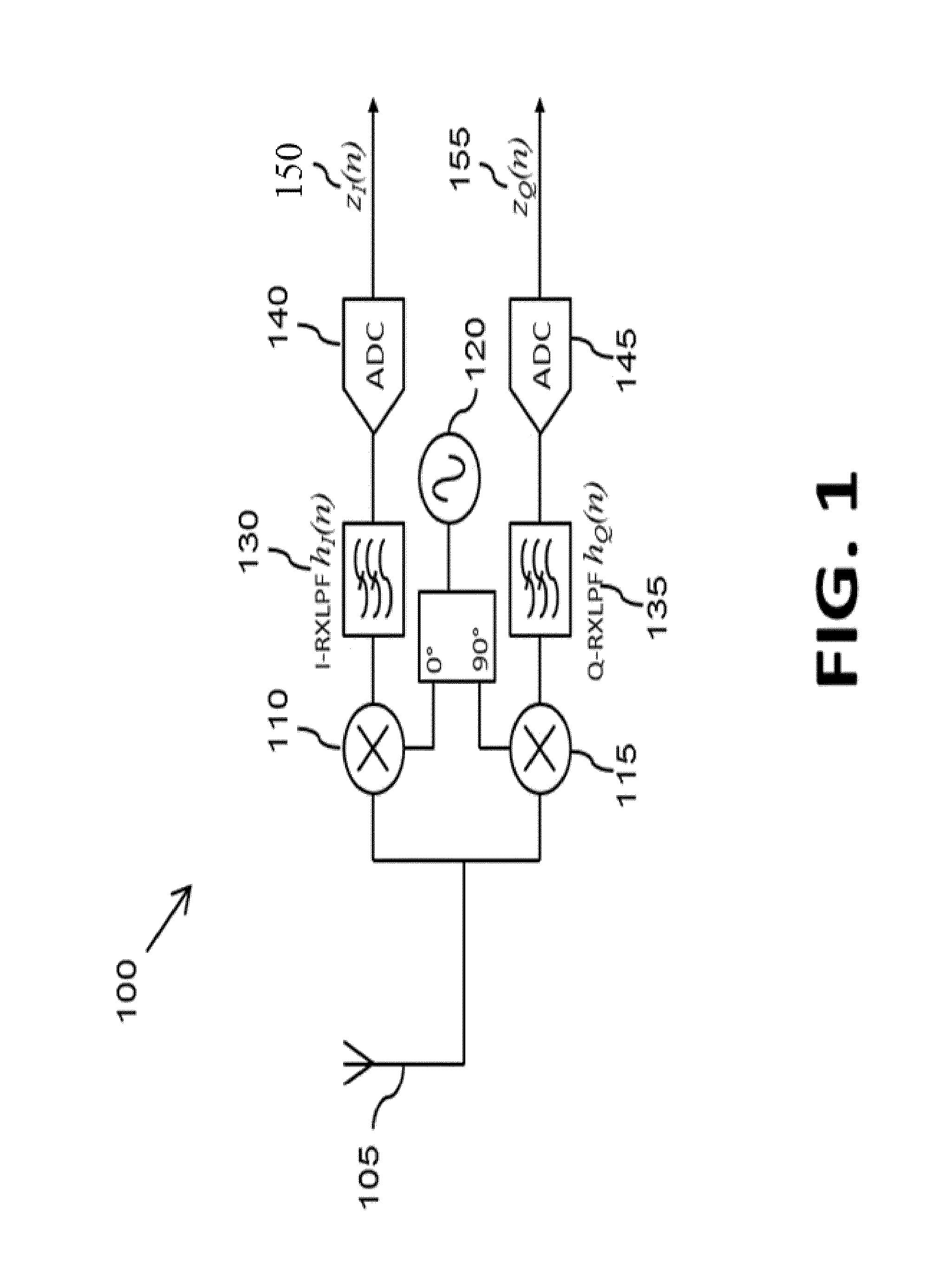
In practical receivers, the analogue components within the in-phase and quadrature branches, and in particular the respective low pass filters 130, 135, tend not to be exactly matched, and thus can degrade the image rejection ratio (IRR) of the receiver, thereby resulting in performance loss.
Furthermore, the use of large bandwidths such as, for example, 20 MHz in LTE and 160 MHz in IEEE 802.11ac, result in significant frequency dependent I / Q imbalances.
Trying to reduce the I / Q imbalance using analogue design would significantly increase the cost of the RF chipset.
However, such a technique requires the transmitter frequency to be offset from the receiver frequency to specific values for configuration, which may require difficult modifications to the transceiver architecture.
Once again, such a technique is deterministic (non-stochastic), and therefor fast.
However, this technique is sensitive to transmitter distortion, such as linearity and harmonics.
In addition to the disadvantages already mentioned, such training based approaches also require modifications in the baseband or RF architectures, and require complex additional circuitry such as envelope detectors or tone-generators.
Furthermore, such training based approaches do not facilitate ‘on-the-fly’ configuration.
However, such a solution using a non-linear iterative technique involves using a matrix inversion, and thus the complexity of such a solution is prohibitive for filter lengths of greater than three.
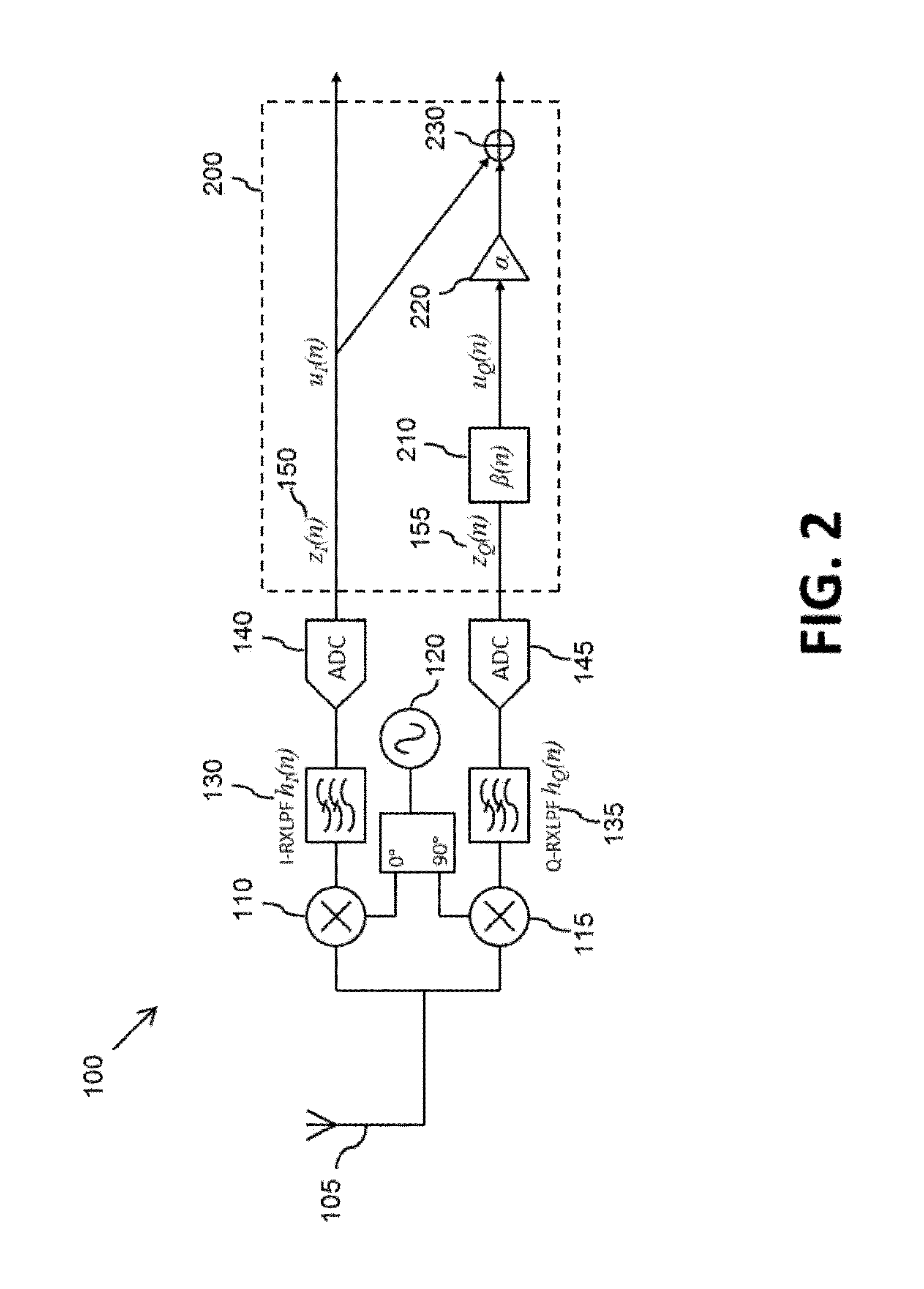
However this method results in an inferior configuration of the FD I / Q imbalance compensation filter (β(n)) 210, and thus an inferior performance of the receiver.
However, it is still a relatively high complexity solution requiring significant processing / memory resources.
Furthermore, the underlying spectral estimation scheme is non-parametric and hence performance is in general poor.
In addition, the performance degrades in a dispersive channel for on-the-fly configuration, and performance is sensitive to spectral nulls resulting in less flexibility in relation to range of sampling rates.
In addition to the disadvantages already mentioned, such known blind algorithm based approaches in general suffer from high-complexity, for example requiring non-linear equations to be solved using iterative methods.
Advantageously, the computational complexity of such a technique is similar to a least mean square (LMS) computation, and thus is significantly lower than for the known blind algorithm techniques.
As such, this technique results in an increased power consumption of the RF circuitry, and also results in a degradation of the noise performance when limited by headroom.
Such increases in power consumption and degradation of the noise performance are particularly problematic for higher frequency designs such as used for LTE and IEEE 802.11ac wireless standards.

Method used


Image

  • Method and apparatus for configuring a frequency dependent I/Q imbalance compensation filter
  • Method and apparatus for configuring a frequency dependent I/Q imbalance compensation filter
  • Method and apparatus for configuring a frequency dependent I/Q imbalance compensation filter

Examples


Embodiment Construction

[0037]Examples of the invention will be described in terms of one or more radio frequency, RF, transceiver modules for use in a wireless communication unit, such as user equipment in third generation partnership project (3GPP™) parlance. However, it will be appreciated by a skilled artisan that the inventive concept herein described may be embodied in any type of RF module, wireless communication unit or wireless transceiver that comprises discrete I-path and Q-path filtering. Furthermore, because the illustrated embodiments of the present invention may for the most part, be implemented using electronic components and circuits known to those skilled in the art, details will not be explained in any greater extent than that considered necessary as illustrated below, for the understanding and appreciation of the underlying concepts of the present invention and in order not to obfuscate or distract from the teachings of the present invention.

[0038]Referring now to FIG. 4, there is illus...


PUM


Abstract

A method of configuring at least one frequency dependent (FD), in-phase / quadrature (I / Q), imbalance compensation filter within a radio frequency (RF) module is described. The method includes applying an input signal to an input of the RF module, receiving a filtered I-path signal for the RF module and deriving at least one I-path filtering estimate value therefrom, receiving a filtered Q-path signal for the RF module and deriving at least one Q-path filtering estimate value therefrom, and configuring the at least one FD I / Q imbalance compensation filter based at least partly on at least one ratio between the derived I-path and Q-path filtering estimate values.

Description

CROSS REFERENCE TO RELATED APPLICATIONS[0001]This application claims the benefit of U.S. provisional application No. 61 / 791,081, filed on Mar. 15, 2013 and incorporated herein by reference.BACKGROUND[0002]1. Field of the Invention[0003]The field of this invention relates to a method and apparatus configuring at least one frequency dependent (FD), in-phase / quadrature (I / Q), imbalance compensation filter within, say, a radio frequency (RF) module.[0004]2. Background of the Invention[0005]A primary focus and application of the present invention is the field of radio frequency (RF) receivers capable of use in wireless telecommunication applications. FIG. 1 illustrates a simplified block diagram of an example of an RF receiver architecture 100 such as may be used in a wireless telecommunication apparatus; for example such as user equipment in third generation partnership project (3GPP™) parlance. In the illustrated example, the RF receiver architecture 100 comprises an in-phase (I) branc...

Claims


Application Information

Patent Timeline
Patent Type & Authority Patents(United States)
IPC IPC(8): H04B1/10H04L27/38H04B17/00
CPCH04L27/3863
Inventor NARASIMHAN, BALACHANDERCHIEN, CHARLESYAN, SHENG-HONGLIANG, PAUL CHENG PO
Owner MEDIATEK SINGAPORE PTE LTD SINGAPORE
Learn More