
Systems and methods for plug load control and management

a plug load and management technology, applied in the direction of process and machine control, computer control, instruments, etc., can solve the problems of increasing the difficulty of controlling and managing, increasing the cost of energy consumption, so as to achieve easy maintenance, minimal time and effort, and energy saving

Inactive Publication Date: 2015-08-25
THINKECO
View PDF13 Cites 9 Cited by
  • Summary
  • Abstract
  • Description
  • Claims
  • Application Information

AI Technical Summary

Benefits of technology

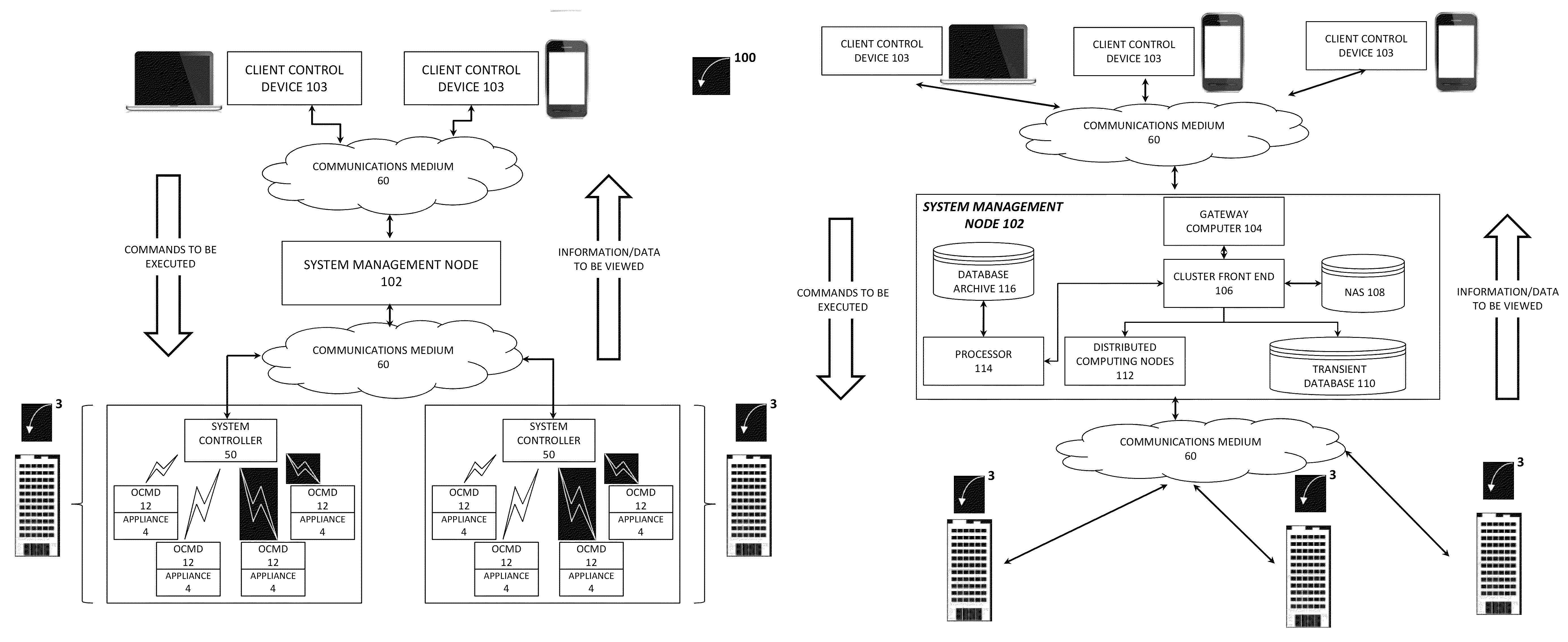
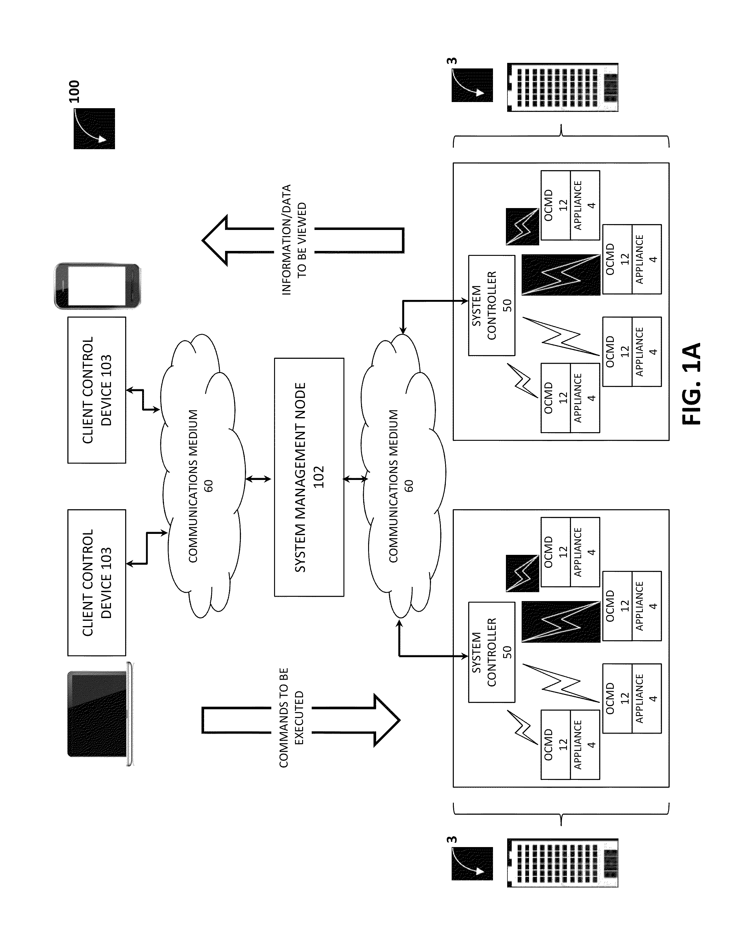
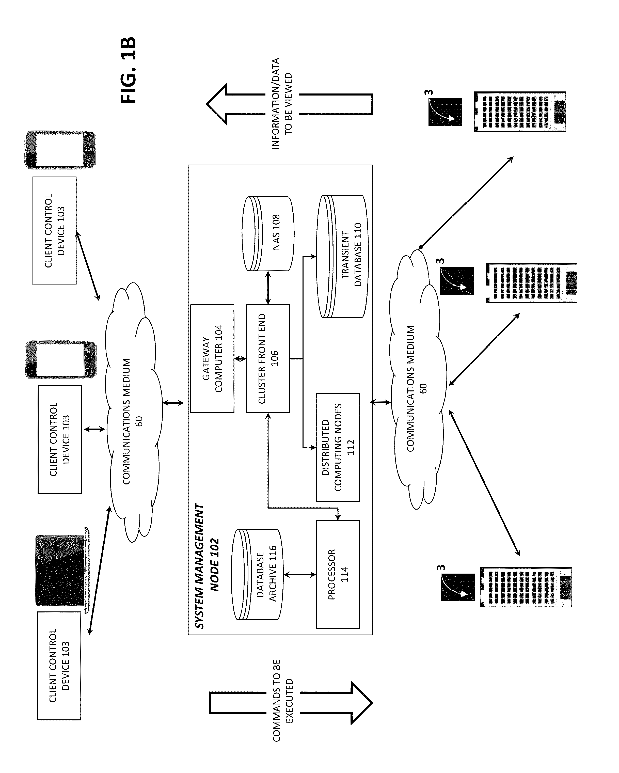
[0011]The methods and systems of the present invention enable intelligent control of plug load devices within commercial or residential settings and permit one to increase energy efficiency and cost savings without compromising safety, comfort or productivity based on one or more of user-generated or event-driven control signals. Within these systems, each outlet control and monitoring device may be associated with one or more corresponding home or office plug load devices (e.g., appliances) and have the ability to shut off power to each of its associated devices at certain periodic, predictable or unpredictable times or during certain periodic, predictable or unpredictable intervals based on control signals received from a system controller. Each OCMD may have onboard memory to execute real-time control signal events and to store historical and / or future scheduled control signal events, as well as device operating information. Thus, in some embodiments, one or more compiled device power state schedules are stored on the OCMD and the system controller transmits information to activate a certain compiled device power state schedule. In other embodiments, the system controller simultaneously transmits the compiled device power state schedule and optionally, an instruction of when to execute it.
[0016]First, various embodiments of the present invention may be scalable, allowing for easy control on a large scale, so that a system administrator or facilities manager, for example, can quickly and seamlessly set energy savings plans for thousands of load devices, (coupled to corresponding OCMDs,) over multiple buildings, using a simple graphical user interface (GUI) and requiring minimal time and effort.
[0017]Second, various embodiments of the present invention may simultaneously be granular, allowing for large numbers, for example, thousands of individual users to have certain control permissions that allow them to override, automatically or manually, an administrator-set energy savings plan for some subset of devices (e.g., the devices at that user's desk). This allows users to easily avoid service interruptions, thereby allowing the control system to seamlessly blend into the individual user's daily routine, minimizing required behavioral change.
[0018]Third, various embodiments of the present invention may be highly flexible in terms of configuration, whereby essentially an unlimited number of permutations and combinations of control can be achieved and executed across numerous critical categories, or dimensions, of control. For example, a given system can have many different energy savings plans, each of which applies to many different devices on many different date ranges, and which are set by many different users, each user having many different scheduling, editing, override control and ownership permissions over many different devices.
[0020]Fifth, various embodiments of the present invention may have extremely high reliability with respect to exercising control over OCMDs and their coupled devices.

Problems solved by technology

Global energy consumption steadily outpaces the growth of economically viable renewable energy, and the amount of available fossil fuel resources continues to dwindle.
Unfortunately, the category of plug loads (which refers to devices that plug into wall sockets and demand electricity) has proven more difficult to control and to manage, and thus it remains largely unaddressed.
Demonstrative of the challenges of improving the efficiency of plug loads is the trend that they, plug loads, outpace growth in commercial floor space to such a degree that the overall energy consumption of commercial buildings is still climbing.
While these technologies extend certain types of control ability to the previously unaddressed category of plug loads, there remain barriers to the practical implementation of a plug load energy efficiency system that have largely prevented integration of plug load control into BAS.

Method used


Image

  • Systems and methods for plug load control and management
  • Systems and methods for plug load control and management
  • Systems and methods for plug load control and management

Examples


Embodiment Construction

[0025]In the following discussion, numerous specific details are set forth in order to provide a thorough understanding of the present invention. Additionally, this specification provides examples and figures in order to illustrate various features. However, those skilled in the art will appreciate that various embodiments of the present invention may be practiced without one or more of the recited specific details. Additionally, within the figures, well-known elements have been illustrated in schematic or block diagram form in order not to obscure the present invention in unnecessary detail. Furthermore, details concerning network communications, electromagnetic signaling techniques and other well-known technologies have not been described in detail because they are well-known to persons of ordinary skill in the art, and recitation of such details is not considered necessary to obtain a complete understanding of the present invention.

[0026]All statements herein reciting principles,...


PUM


Abstract

The present invention is directed to methods and systems for control of loads that are connected to plugs. Through the use of various embodiments of the present invention one may allow a plurality of users to control the use of power by individual loads and dynamically configurable sets of loads with ease, on both small and large scales. Users may select from energy savings plans to generate compiled device power state schedules that automatically cause devices to enter power savings modes as pre-determined times. Consequently, one can efficiently manage plug load electricity usage in a plurality of buildings.

Description

FIELD OF THE INVENTION[0001]The present invention relates to the control of plug load devices.BACKGROUND OF THE INVENTION[0002]Global energy consumption steadily outpaces the growth of economically viable renewable energy, and the amount of available fossil fuel resources continues to dwindle. Consequently, energy efficiency remains an important initiative. By improving efficiency, the global community can reduce energy consumption, and thereby conserve resources for the future without decreasing quality of life in the present.[0003]One movement toward improving energy efficiency is to use electronic devices, such as sensors and microcontrollers in order to create intelligent, computerized networks to control and to monitor certain energy consuming features of buildings. Over the past decade, such systems, called building automation systems (BAS), have significantly improved the efficiency of certain energy end-use categories such as heating, ventilation and air conditioning (HVAC) ...

Claims


Application Information

Patent Timeline
Patent Type & Authority Patents(United States)
IPC IPC(8): G06F19/00G05B15/02G06Q50/06
CPCG06Q50/06G05B15/02
Inventor SCHMIDT, JAMESLEVISHIMADA, JUNSHIBATA, MEIHERTZ-SHARGEL, BEN
Owner THINKECO
Learn More