
Dual reflector system for linear lamp illuminators

a technology of linear lamps and reflectors, applied in the field of linear lamp illuminator systems, can solve the problems of heavy and expensive, waste of most of the light generated by the lamp, and large and expensive reflectors

Active Publication Date: 2015-08-25
MACDONALD DETTWILER & ASSOC INC
View PDF18 Cites 6 Cited by
  • Summary
  • Abstract
  • Description
  • Claims
  • Application Information

AI Technical Summary

Benefits of technology

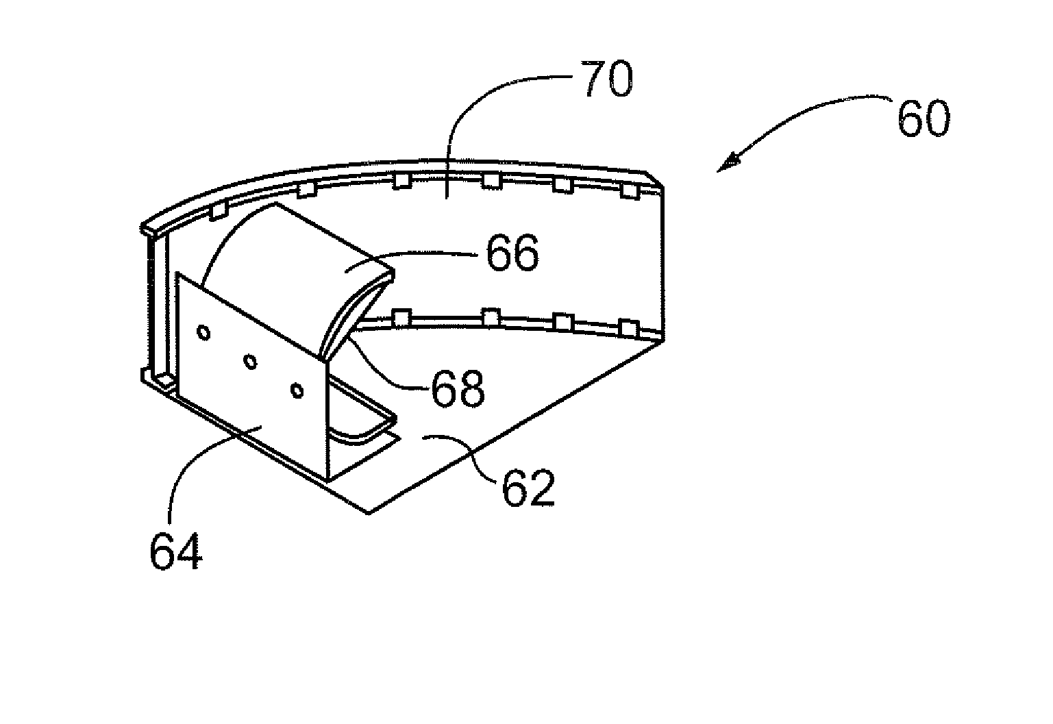
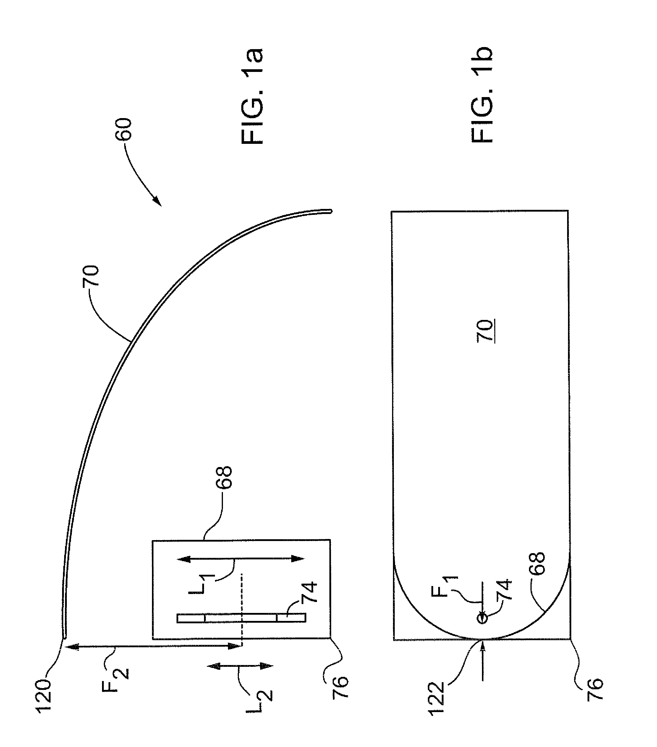
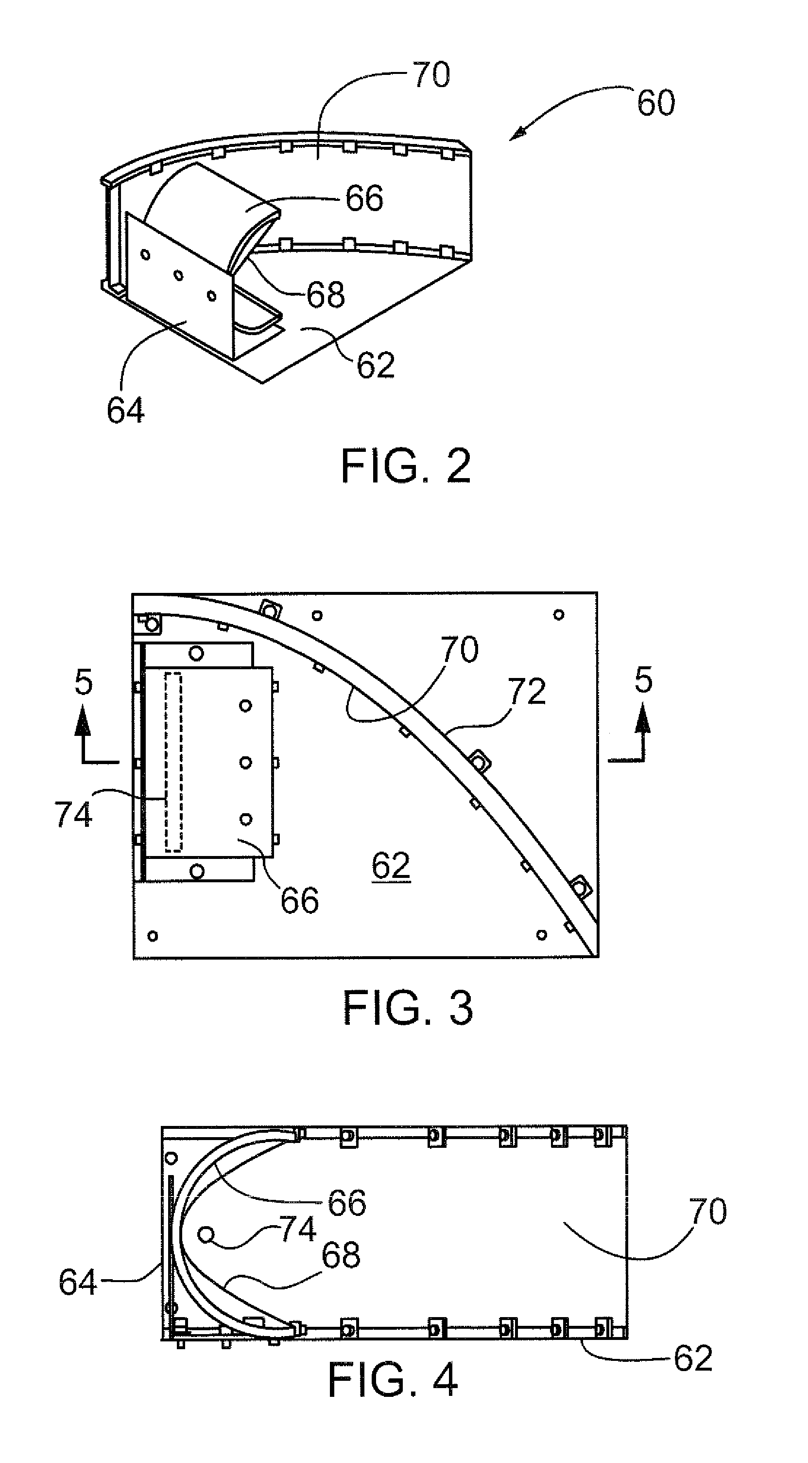
The present invention is about an illuminator system that uses a dual reflector system and a linear light source. The reflectors are positioned so that the light emitted by the linear light source is reflected and collimated in two planes. The light source can be a flash lamp, continuous wave cylindrical linear light source, or other light sources. The reflectors can be milled or flexible sheets mounted to inserts and can be adjusted in position and orientation. The invention provides a compact and efficient illuminator system that can be used for various lighting purposes.

Problems solved by technology

Unfortunately these standard methods have a number of drawbacks.
Cylindrical reflectors can only collimate the light in one plane and have a very wide beam in a plane orthogonal thereto, so most of the light generated by the lamp is wasted.
Adding a cylindrical fresnel lens helps, but the lens must have a long focal length and large aperture which makes it heavy and expensive.
Refractive elements can also separate the colours of the light due to dispersion, which is often undesirable in applications involving optical sensors.
For long flashlamps, this imposes a large diameter for the reflector, making the reflector large and expensive.
Further, some configurations of paraboloid reflectors such as the ones found in U.S. Pat. Nos. 4,210,954 and 3,254,342 may produce a doughnut beam pattern which is often undesirable for imaging applications.

Method used


Image

  • Dual reflector system for linear lamp illuminators
  • Dual reflector system for linear lamp illuminators
  • Dual reflector system for linear lamp illuminators

Examples


Embodiment Construction

[0044]Generally speaking, the systems described herein are directed to a dual reflector system for linear lamp illuminators. As required, embodiments of the present invention are disclosed herein. However, the disclosed embodiments are merely exemplary, and it should be understood that the invention may be embodied in many various and alternative forms. The Figures are not to scale and some features may be exaggerated or minimized to show details of particular elements while related elements may have been eliminated to prevent obscuring novel aspects. Therefore, specific structural and functional details disclosed herein are not to be interpreted as limiting but merely as a basis for the claims and as a representative basis for teaching one skilled in the art to variously employ the present invention. For purposes of teaching and not limitation, the illustrated embodiments are directed to dual reflector system for linear lamp illuminators.

[0045]FIGS. 1a and 1b show respectively a to...


PUM


Abstract

The present invention provides an illuminator system comprising a dual reflector system and a linear light source. The dual reflector system comprises a primary and secondary generally cylindrical reflector, which collimate light from a linear light source in two planes. The linear light source may comprise many light emitting devices, and may emit light in a strobe or continuous fashion. The reflectors may be of many cylindrical shapes, and may include additional mirror segments to capture light otherwise not collimated. Further, the reflectors may be in various configurations of position and orientation with respect to one another, and may be adjustable in this respect. The system is more efficient than existing illuminators, is compact, all reflective (no color), lightweight, simple and inexpensive to manufacture. The system has applications to many fields including machine vision, surveillance, spectroscopic inspection of materials, and converting linear light sources into rectangular beam spot lights.

Description

FIELD OF THE INVENTION[0001]This invention generally relates to illuminator systems, and more specifically a linear lamp illuminator system with a dual reflector system.BACKGROUND OF THE INVENTION[0002]Flashlamps are often used as illumination sources for machine vision or surveillance cameras. However, the flashlamp emits light in all directions, so a collimating optical system must be used to concentrate the light onto the target of interest. Cylindrical parabolic or paraboloid reflectors are often used to collimate the light from linear flashlamps, sometimes in conjunction with a fresnel refractive lens. Unfortunately these standard methods have a number of drawbacks.[0003]Cylindrical reflectors can only collimate the light in one plane and have a very wide beam in a plane orthogonal thereto, so most of the light generated by the lamp is wasted. Adding a cylindrical fresnel lens helps, but the lens must have a long focal length and large aperture which makes it heavy and expensiv...

Claims


Application Information

Patent Timeline
Patent Type & Authority Patents(United States)
IPC IPC(8): F21V7/06F21V7/00F21V7/04G03B15/03F21V7/22F21Y103/00
CPCF21V7/06F21V7/005F21V7/0033F21V7/04G03B15/03F21V7/22F21Y2103/00G03B2215/0582F21V7/24
Inventor GREGORIS, DENNIS
Owner MACDONALD DETTWILER & ASSOC INC
Learn More