Computed radiography imaging plates and associated methods of manufacture

a radiography and computed radiography technology, applied in the field of medical and industrial imaging, can solve the problems of preventing the proper placement of such intensifying screens and the use of intensifying screens is extremely difficult, and achieve the effects of reducing internal scattering, increasing resolution, and reducing the radiation dose needed for radiography

Active Publication Date: 2015-08-18
CONSOLIDATED NUCLEAR SECURITY
View PDF6 Cites 6 Cited by
  • Summary
  • Abstract
  • Description
  • Claims
  • Application Information

AI Technical Summary

Benefits of technology

[0019]In the present disclosure, a novel screen (also referred to herein as a layer, filter, grid, and / or intensifier) is coupled to the phosphor layer, allowing electrons and / or low energy x-rays to impart their energy on the phosphor layer, while decreasing internal scattering and increasing resolution. The radiation dose needed to perform radiography can also be reduced as a result.
[0020]Thus, the present disclosure provides a novel process for manufacturing and design of a CR imaging plate that provides significant improvement in resolution for CR systems. This design incorporates a metallic screen or other metallic structure as the phosphor layer's substrate backing, as opposed to a conventional plastic substrate. This design places the phosphor layer in intimate contact with the intensifying screen. As an added advantage, the metallic substrate can be designed to act as a secondary scatter filter for the phosphor layer. A second, and potentially mutually non-exclusive, mechanism for accomplishing intensification (i.e., resolution enhancement / exposure reduction) is to intersperse finely divided metal or metallic compounds into the phosphor layer to achieve the intensification at the grain level of the phosphor.
[0021]Previous to the present disclosure, the conventional plastic substrate on commercially-available products has its own luminescence that interferes with the images. This problem is especially apparent in higher-energy x-ray applications. With current imaging plate designs, the use of intensifying screens is extremely difficult due to proximity limitations inherent in the current imaging plate designs, which incorporate a poly substrate on one side of the phosphor layer with a protective coating on the other side of the phosphor layer, thereby preventing the proper placement of such intensifying screens. With the use of intensifiers, as in the present disclosure, and with an increase in resolution, there is the potential to greatly reduce specimen exposure in low-energy (medical) x-ray operations, for example.

Problems solved by technology

This problem is especially apparent in higher-energy x-ray applications.
With current imaging plate designs, the use of intensifying screens is extremely difficult due to proximity limitations inherent in the current imaging plate designs, which incorporate a poly substrate on one side of the phosphor layer with a protective coating on the other side of the phosphor layer, thereby preventing the proper placement of such intensifying screens.

Method used


Image

  • Computed radiography imaging plates and associated methods of manufacture
  • Computed radiography imaging plates and associated methods of manufacture

Examples


Embodiment Construction

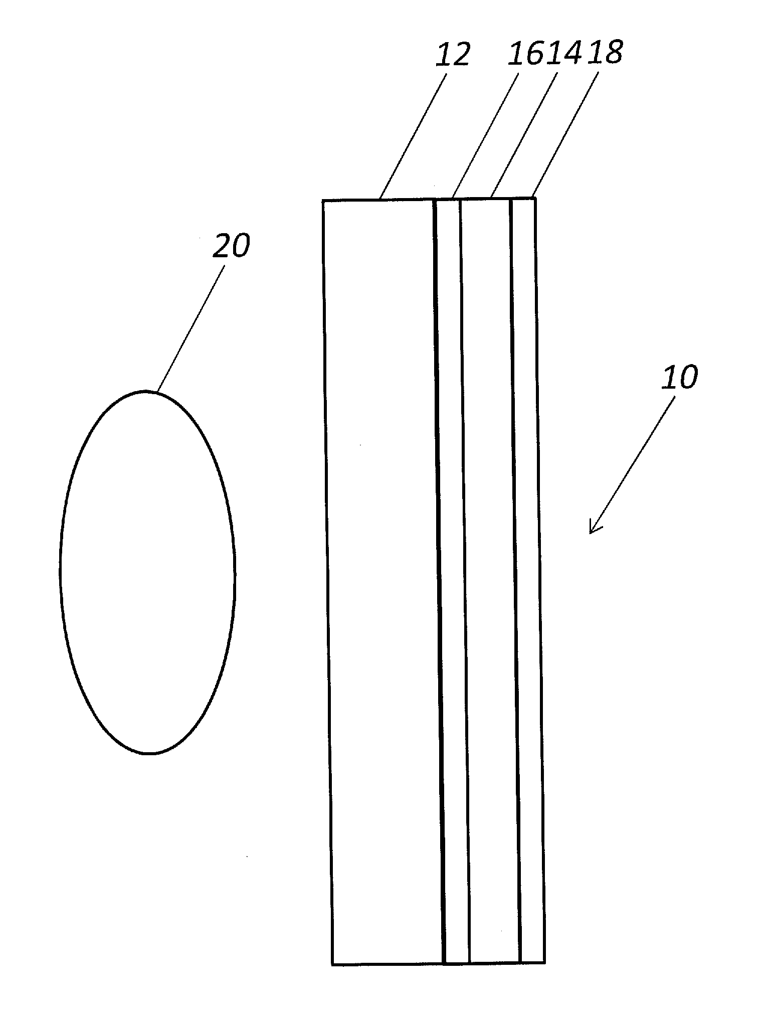
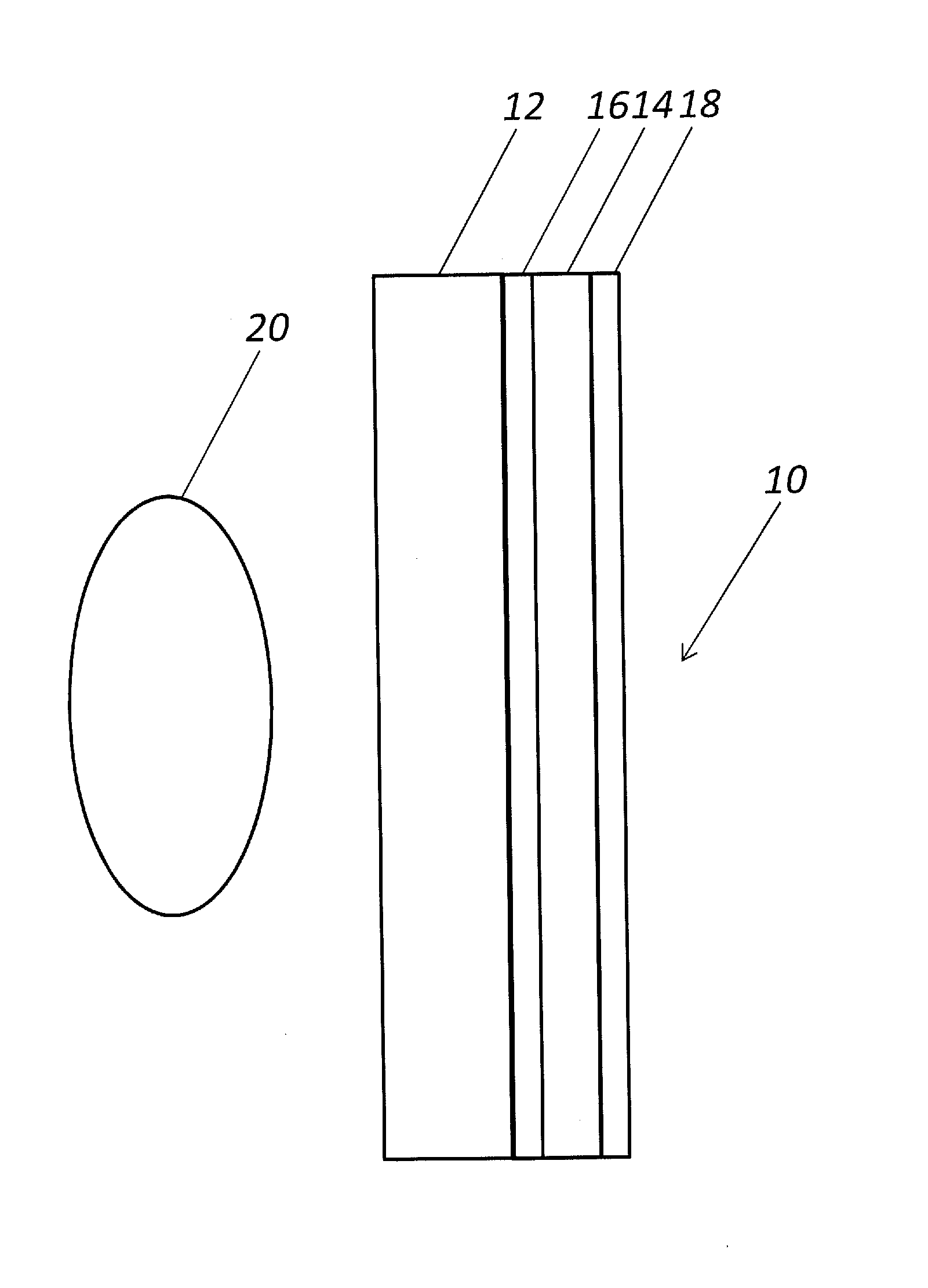
[0026]Referring specifically to FIG. 1, in one exemplary embodiment of the CR imaging plate 10 of the present disclosure, a metallic or other similar high density material layer 12 (also referred to herein as the intensifying layer 12) is coupled to the phosphor layer 14. Reflective or anti-reflective layers or surfacing 16 optionally may be disposed between the intensifying layer 12 and the phosphor layer 14, depending on desired use of the imaging plate 10. The thickness and material composition of the intensifying layer 12 will affect the effective quantum efficiency of the detector (not illustrated) and change the dose response curves and the effective resolution. Different thicknesses and material compositions of the intensifying layer 12 will be better suited for different energies of x-rays and applications.

[0027]The conventional backing layer (not illustrated) may be able to be removed and its construction is less vital to the present disclosure. It may still be needed to pr...


PUM


Abstract

Computed radiography imaging plates incorporating an intensifying material that is coupled to or intermixed with the phosphor layer, allowing electrons and / or low energy x-rays to impart their energy on the phosphor layer, while decreasing internal scattering and increasing resolution. The radiation needed to perform radiography can also be reduced as a result.

Description

CROSS-REFERENCE TO RELATED APPLICATION[0001]The present patent application / patent claims the benefit of priority of U.S. Provisional Patent Application No. 61 / 786,749, filed on Mar. 15, 2013, and entitled “COMPUTED RADIOGRAPHY IMAGING PLATES AND ASSOCIATED METHODS OF MANUFACTURE,” the contents of which are incorporated in full by reference herein.STATEMENT REGARDING FEDERALLY SPONSORED RESEARCH OR DEVELOPMENT[0002]The U.S. Government has rights to the present disclosure pursuant to Contract No. AC05-00OR22800 between the U.S. Department of Energy and Babcock and Wilcox Technical Services Y-12, LLC.FIELD OF THE DISCLOSURE[0003]The present disclosure relates generally to the medical and industrial imaging fields. More specifically, the present disclosure relates to computed radiography (CR) imaging plates and associated methods of manufacture.BACKGROUND OF THE DISCLOSURE[0004]Computed radiography (CR) is a reusable digital radiography modality. It utilizes reusable imaging plates inco...

Claims


Application Information

Patent Timeline
Patent Type & Authority Patents(United States)
IPC IPC(8): G01J1/58G01T1/20G21K4/00G03B42/02
CPCG03B42/02G01T1/2012G21K2004/06G21K2004/04
Inventor HENRY, NATHANIEL F.MOSES, ALEX K.
Owner CONSOLIDATED NUCLEAR SECURITY
Why Eureka
Try Eureka