
Method of deposition

a technology of deposition and evaporation, which is applied in the direction of vacuum evaporation coating, coating, electric discharge tube, etc., can solve the problems of sealing, sealing becomes a problem, and may not achieve efficient production, so as to reduce the production cycle of the product having the thin film, the effect of reducing the time of deposition and reducing the time of long tim

Inactive Publication Date: 2015-08-18
JAPAN STEEL WORKS LTD
View PDF16 Cites 0 Cited by
  • Summary
  • Abstract
  • Description
  • Claims
  • Application Information

AI Technical Summary

Benefits of technology

The invention describes a method for efficiently depositing material onto a workpiece by integrating assisting members with the workpiece. This eliminates the need for the assisting members to be cut off when interfering with the product. The assisting members are easy to cut off and can be formed of multiple rod-shaped members, making the cutting process easier. This method reduces the deposition time and production cycle of the product, ultimately improving efficiency and productivity.

Problems solved by technology

For example, a time when the workpiece is molded in the mold and a time when the deposition chamber is used and the deposition is performed, are not concurrent, so that waiting time occurs in order to match these timings, and efficient production may not be achieved.
In addition, since an opening of the deposition chamber is in close contact with a parting surface of the mold, and a vacuum chamber is formed inside thereof, there is also a problem of sealing.
However, since an opening of the deposition chamber and a parting surface of the mold have different members from each other according to their purpose and have different configurations, sealing becomes a problem.
Furthermore, in order for insertion and removal from the large deposition chamber between the molds which covers the concave portion of the mold, an amount of a mold opening of the molds becomes large, and a robot for inserting and removing the deposition chamber to and from the molds also becomes large.
Accordingly, target particles are difficult to be attached to the deposition surface which does not face the target material.
Thus, there are problems that time is further required to the deposition operation and the cost thereof increases.

Method used


Image

  • Method of deposition
  • Method of deposition
  • Method of deposition

Examples


Embodiment Construction

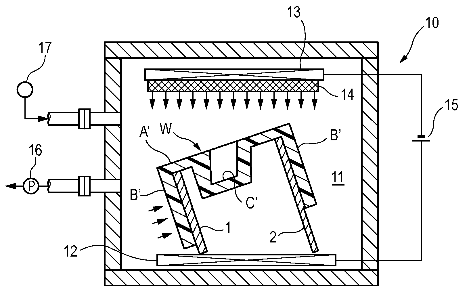
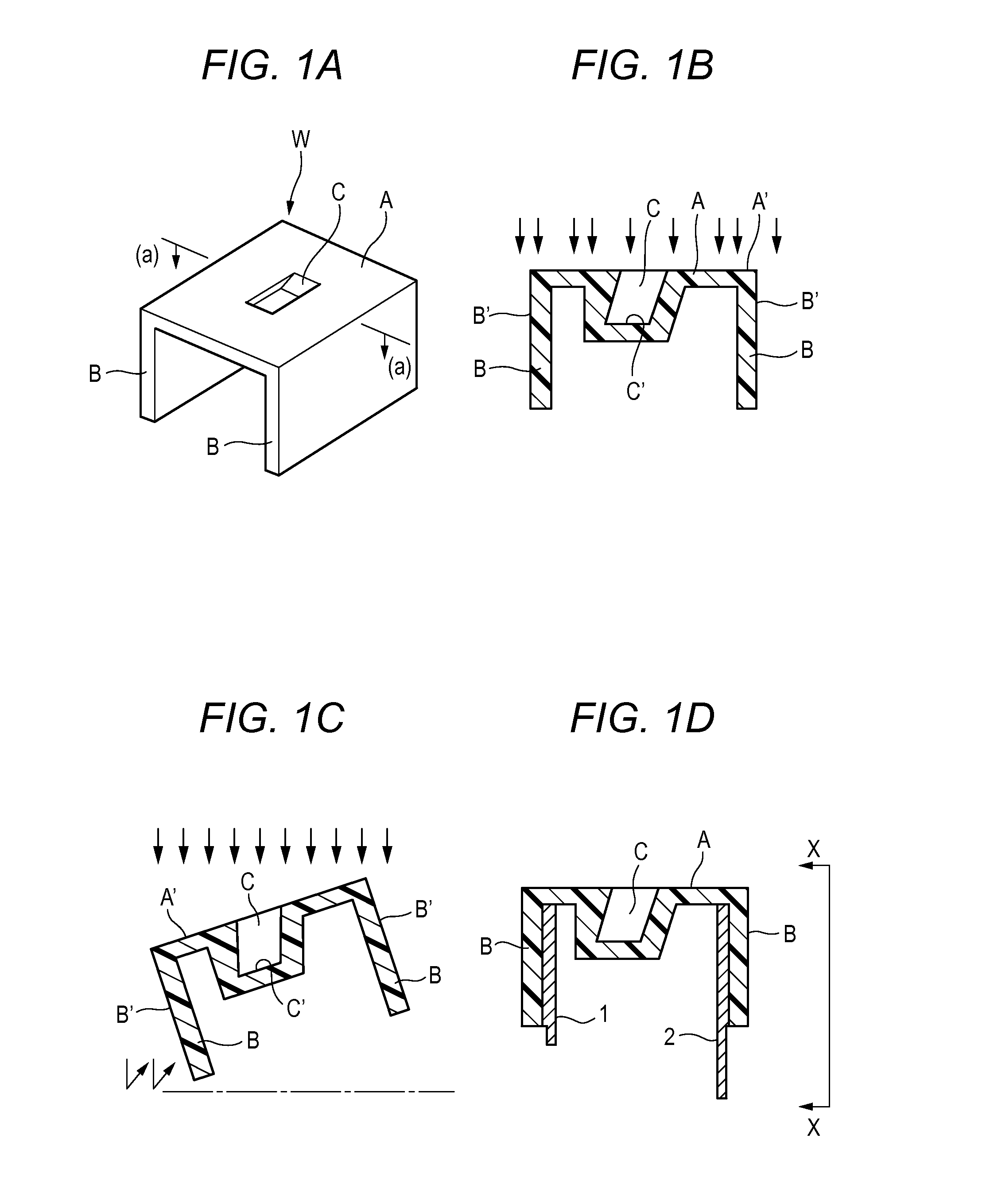
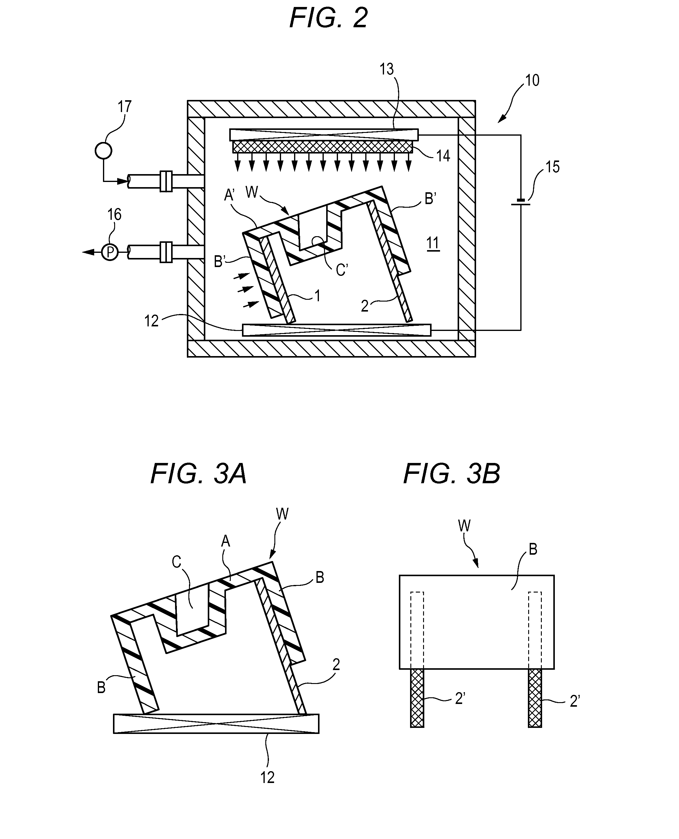
[0028]Hereinafter, an embodiment of the invention will be described with reference to the drawings. According to the embodiment, as shown in FIGS. 1A and 1B, a workpiece W for deposition is configured by a top portion A and both side portions B and B which are substantially at right angles with the top portion A. The workpiece for deposition generally has a shape in which groove-formed steel is cut. Thus, the workpiece W for deposition has a relatively deep concave portion C toward the back side of the top portion A. The concave portion C is inclined with respect to the planar top portion A. Accordingly, target particles, which are illustrated by a plurality of arrows in FIG. 1B, are difficult to reach deposition surfaces B′ and B′ of the both side portions B and B, and a deposition bottom surface C′ of the concave portion C. The surfaces become deposition surfaces or deposition portions B′, B′ and C′ where the target particles are difficult to reach. The embodiment according to the...


PUM

PropertyMeasurementUnit
angleaaaaaaaaaa
lengthaaaaaaaaaa
thicknessaaaaaaaaaa

Abstract

A method of deposition is provided in which a deposition operation can be immediately performed when a workpiece for deposition is carried into a deposition chamber irrespective of a shape or a structure of the workpiece for deposition. The workpiece for deposition is integrally molded with an assisting member, which is configured to maintain the workpiece for deposition in a predetermined orientation such that a deposition surface or a deposition portion thereof faces a target material when the workpiece for deposition is carried into a deposition chamber and is placed on a deposition stand, when the workpiece for deposition is injection-molded; and the workpiece for deposition is carried into the deposition chamber and is deposited.

Description

[0001]This application claims priority from Japanese Patent Application No. 2011-198043 filed on Sep. 12, 2011, the entire subject-matter of which is incorporated herein by reference.BACKGROUND OF THE INVENTION[0002]1. Field of the Invention[0003]The present invention relates to a method of deposition in which a workpiece for deposition such as a substrate made of resin is carried into a vacuum chamber or a deposition chamber and then a thin film is formed on a predetermined surface of the workpiece.[0004]2. Description of the Related Art[0005]Some deposition workpieces have a film thickness of the order of several μm. An automobile headlamp is one example of such a deposition workpiece. The headlamp is made by a deposition device or a vapor deposition device. The deposition device may be applied to manufacturing of a magnetic disk, manufacturing of a metallic film of a recording surface of a CD / DVD, manufacturing of a transparent electrode of a liquid crystal display or manufacturi...

Claims


Application Information

Patent Timeline
Patent Type & Authority Patents(United States)
IPC IPC(8): C23C14/34H01J37/20C23C14/50
CPCC23C14/34C23C14/50H01J37/20H01J2237/2007
Inventor NISHIDA, SHOSO
Owner JAPAN STEEL WORKS LTD
Learn More