
Vibration systems and methods

a vibration system and vibration technology, applied in the field of vibration systems, can solve the problems of piezoelectric ring naturally transmitting such vibration to the vibrating plate, and the installation of ultrasonic transducers directly onto rigid frames or housings, etc., and achieve the effect of simple and inexpensive system manufactur

Active Publication Date: 2015-08-18
STAMFORD DEVICES LTD
View PDF552 Cites 27 Cited by
  • Summary
  • Abstract
  • Description
  • Claims
  • Application Information

AI Technical Summary

Benefits of technology

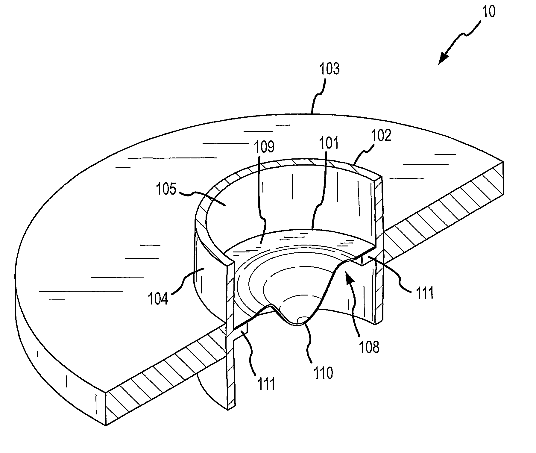
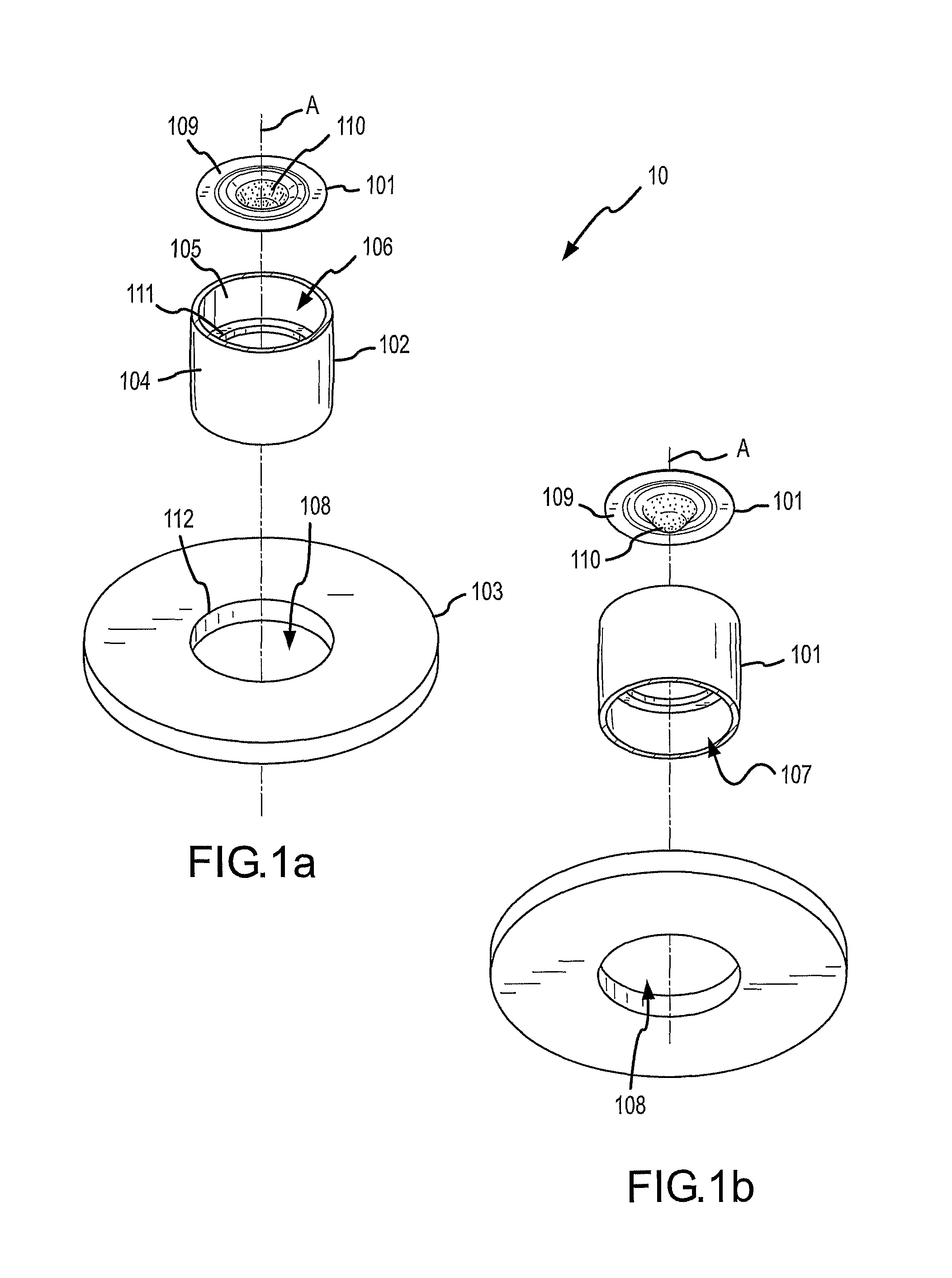
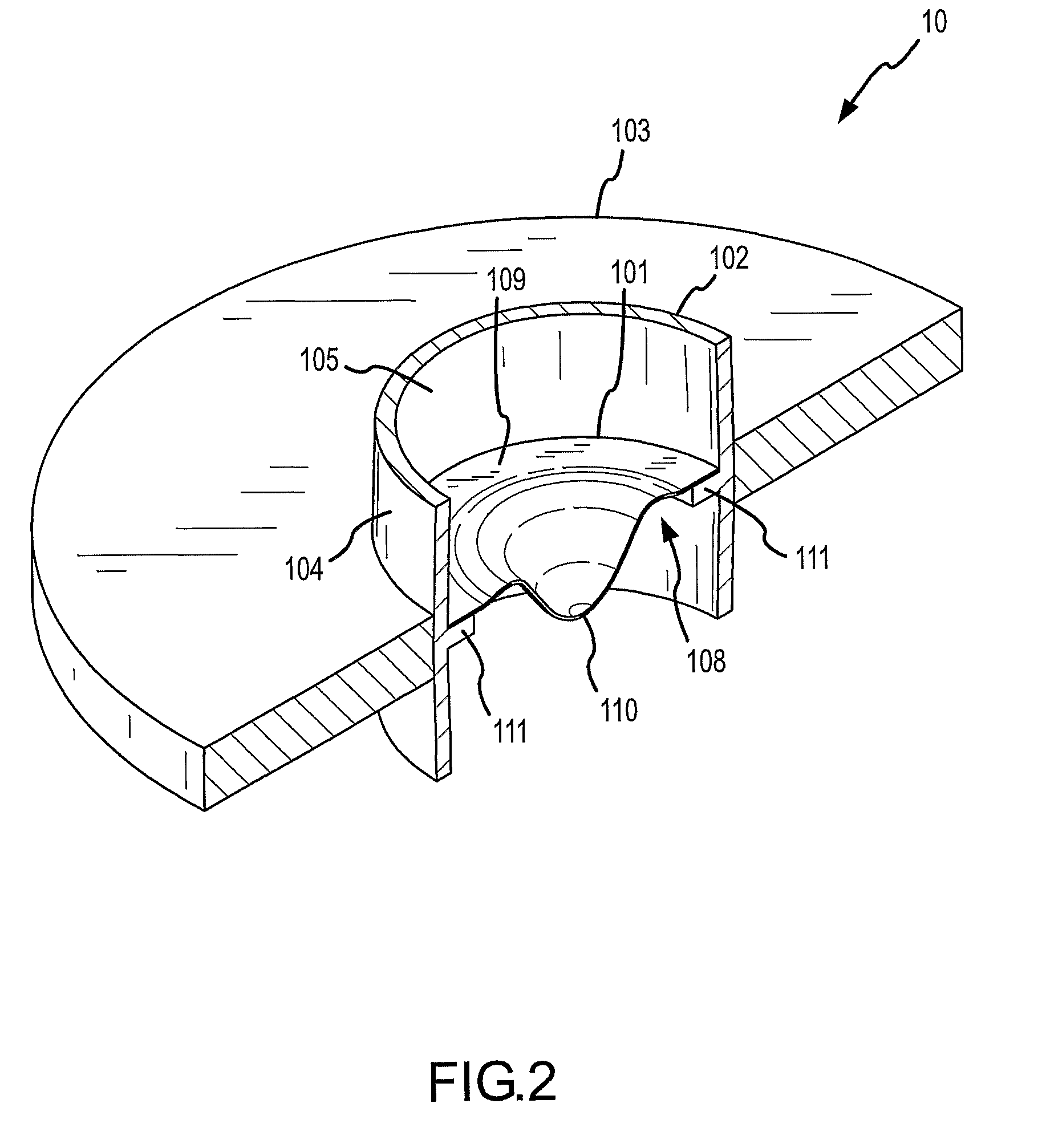
The present invention provides a vibration system that efficiently transfers radial vibration from a vibration-inducing member to produce axial vibration in a vibratable member through a support member that filters out undesirable vibration. The vibration-inducing member may be an annular piezoelectric transducer having a central opening, and the vibratable member may be a thin circular plate. The support member may have a circular cross-section for holding the circular plate. The system effectively isolates the vibration-inducing member from contact with liquids and is therefore particularly adapted for operation in a fluid medium, e.g. in an aerosolizer environment. The invention provides a simple and inexpensive method for self-aligning the components of a vibration system. The invention provides a vibration system that can efficiently produce aerosol and prevent contamination of the components. The reservoir and the tubular member containing the aperture plate may be integrated as a single unit, and the piezoelectric ring may be easily removed without potential contamination from substances within the reservoir or tubular member, or from aerosol produced by the aperture plate.

Problems solved by technology

Installing an ultrasonic transducer directly onto a rigid frame or housing, such as taught by Maehara, is also problematic.
Another problem with prior art arrangements is that the piezoelectric ring naturally vibrates in 3 directions (i.e., X, Y and Z axes) and transmits such vibration to the vibrating plate.
Such material, while providing electrical insulation, also has energy-absorbing characteristics that dampen the oscillation amplitude of the piezoelectric transducer and therefore has an adverse effect of the efficiency of the device.
One issue with aerosolizers (especially those used for medical applications using highly corrosive liquids) is contamination and corrosion of parts.
Many of these parts are difficult to clean and, since piezoelectric transducers and their associated electronics can be relatively expensive, making them disposable may not be economically feasible.

Method used


Image

  • Vibration systems and methods
  • Vibration systems and methods
  • Vibration systems and methods

Examples


Embodiment Construction

[0033]All publications, patents and patent applications cited herein, whether supra or infra, are hereby incorporated by reference in their entirety to the same extent as if each individual publication, patent or patent application was specifically and individually indicated to be incorporated by reference.

[0034]It must be noted that, as used in this specification and the appended claims, the singular forms “a,”“an” and “the” include the plural unless the content clearly dictates otherwise.

[0035]Reference herein to “one embodiment”, “one version” or “one aspect” shall include one or more such embodiments, versions or aspects, unless otherwise clear from the context.

[0036]In one or more embodiments, the vibration system of the present invention comprises a vibratable plate, a support member surrounding the vibratable plate, and a vibration-inducing member surrounding the support member, wherein the vibration-inducing member is configured to radially expand and contract against the su...


PUM

PropertyMeasurementUnit
thicknessaaaaaaaaaa
thicknessaaaaaaaaaa
sizeaaaaaaaaaa

Abstract

In one arrangement, a vibration system includes a vibratable plate, a support member surrounding the vibratable plate, and a vibration-inducing member surrounding the support member. The vibration-inducing member is configured to radially expand and contract against the support member so as to produce axial vibration of the vibratable plate. In another arrangement, the vibratable plate has an outer circumference; a tubular member is concentrically disposed about the outer circumference of the plate, and an annular vibration-inducing member is concentrically disposed about the outer circumference of the tubular member. The vibration-inducing member is preferably a piezoelectric ring that is radially expandable and contractable against the wall of the tubular member to cause the plate to vibrate in the axial direction.

Description

CROSS-REFERENCE TO RELATED APPLICATIONS[0001]This application is a 35 USC §371 application of International Application No. PCT / US2006 / 014654 filed Apr. 17, 2006, designating the United States, which claims priority to U.S. Application No. 60 / 684,720 filed May 25, 2005, now abandoned, both of which are hereby incorporated by reference in their entirety.BACKGROUND OF THE INVENTION[0002]This invention relates generally to a vibration system that efficiently transfers radial vibration from a vibration-inducing member to produce axial vibration in a vibratable member through a support member that filters out undesirable vibration. In preferred embodiments, a piezoelectric transducer imparts ultrasonic oscillation to a vibratable plate, particularly a vibrating aperture (orifice) plate of an aerosol generator device, wherein the vibrating plate is perforated with holes and is operable in a fluid medium. The invention may also useful in the field of ultrasonic wave transmission in a fluid...

Claims


Application Information

Patent Timeline
Patent Type & Authority Patents(United States)
IPC IPC(8): A61M15/00B05B1/00B05B17/00A61M16/00B05B1/08B05B3/04A61M11/00B05B17/06B05B3/02B05B1/26B05B17/04H10N30/20H10N30/88
CPCB05B17/0676A61M15/00A61M15/009B05B1/00B05B17/00B05B17/04B05B17/06B05B17/0638B05B17/0646Y10T29/42B05B11/04B05B11/02A61M15/0085H10N30/20H10N30/88
Inventor IVRI, YEHUDA
Owner STAMFORD DEVICES LTD
Learn More