Memory timing optimization using pattern based signaling modulation

a pattern based signaling and memory timing technology, applied in the direction of electric digital data processing, static storage, instruments, etc., can solve the problem of diminishing the timing margin of placing a common dll

Inactive Publication Date: 2015-08-11
INTEL CORP
View PDF6 Cites 0 Cited by
  • Summary
  • Abstract
  • Description
  • Claims
  • Application Information

AI Technical Summary

Problems solved by technology

However, the available timing margin for placing a common DLL diminishes when signaling at higher speeds.

Method used


Image

  • Memory timing optimization using pattern based signaling modulation
  • Memory timing optimization using pattern based signaling modulation
  • Memory timing optimization using pattern based signaling modulation

Examples


Embodiment Construction

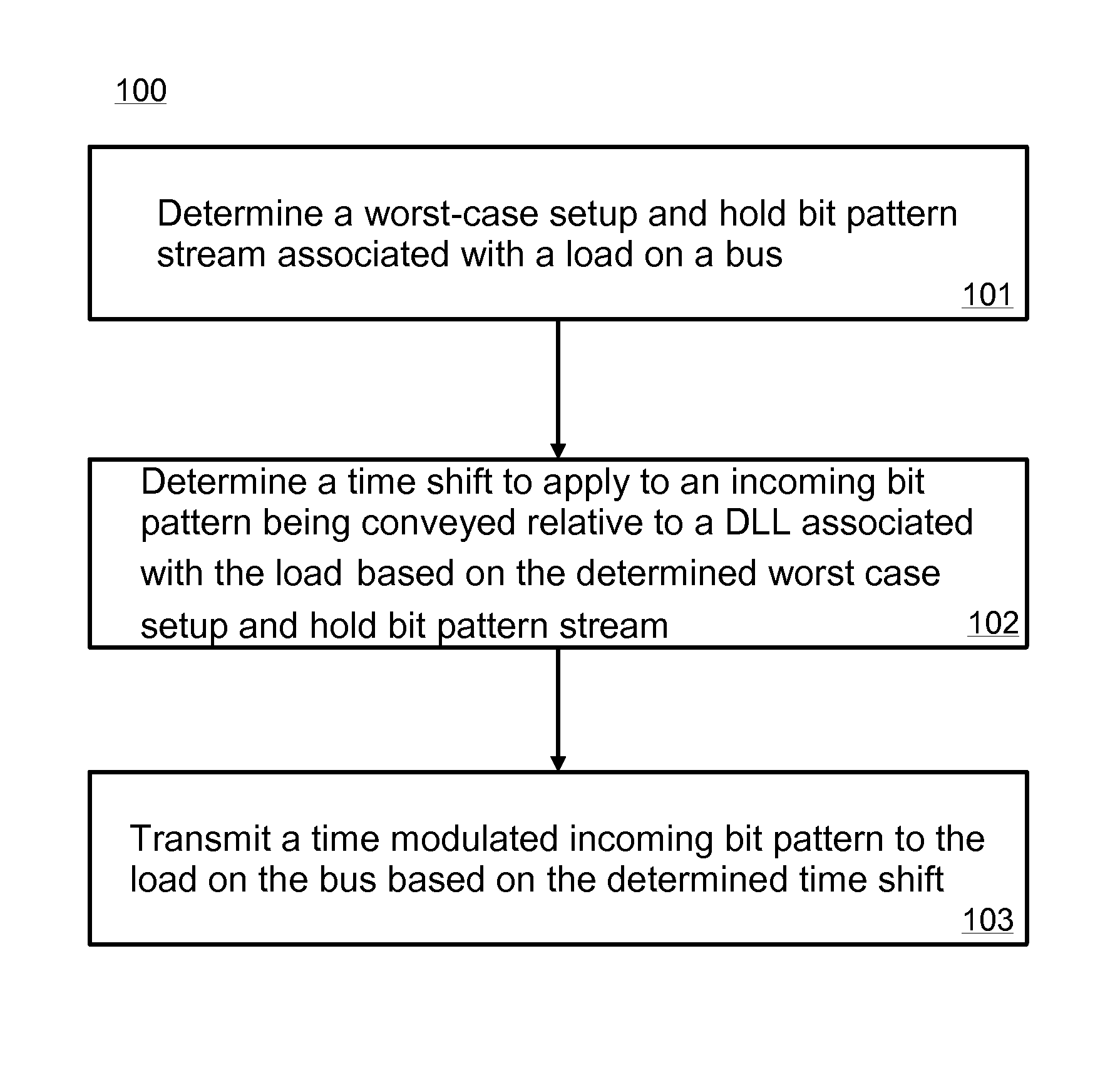
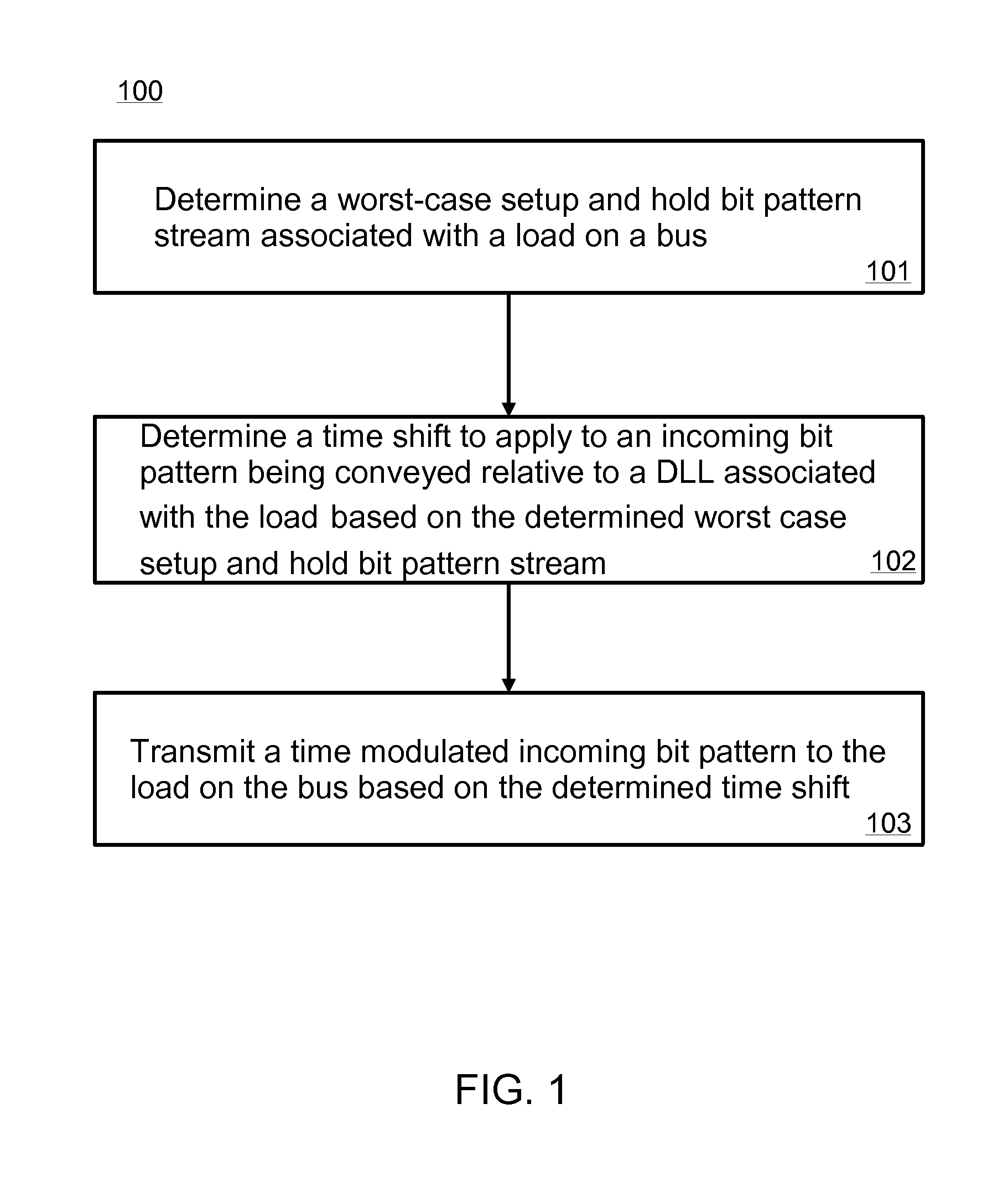
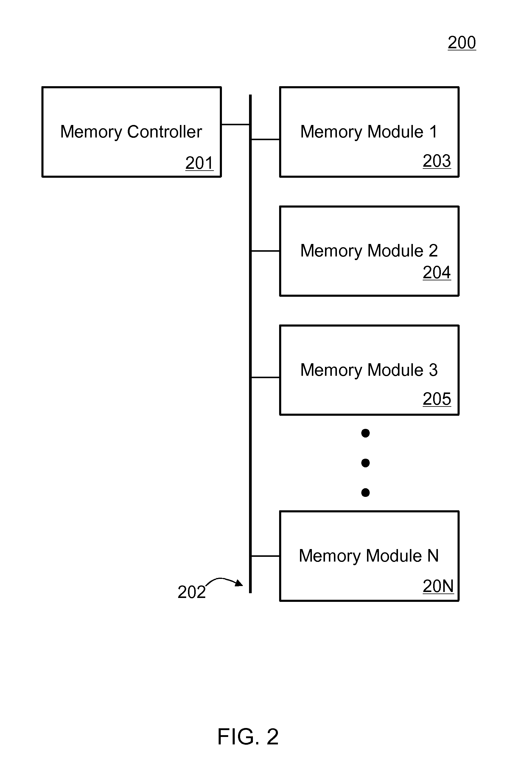
[0007]Referring now to FIG. 1, an embodiment of a method 100 is illustrated. The method 100 may relate to delaying or advancing a relative timing between the incoming bit pattern on the bus and the DLL circuit associated with a memory controller to ensure a greater timing margin on a single or multi-load bus. The method 100 may be performed by an apparatus such as that described with respect to FIG. 3 or by a memory controller such as that described with respect to FIG. 2 or FIG. 3. Furthermore, the method 100 may be embodied on a medium such as a multi-purpose register (“MPR”) which can be preloaded with a limited set of bit patterns that may be used to calibrate the relative advance / retard between an incoming bit pattern on a bus and a DLL associated with the memory controller.

[0008]At 101, a worst-case setup and hold bit pattern associated with a load on a bus is determined. In some embodiments, the worst-case setup and hold bit pattern may be determined for every load on the bus...


PUM


Abstract

According to some embodiments, a method and apparatus are provided to determine a worst-case setup and hold bit pattern stream associated with a load on a bus, and determine a time shift to apply to an incoming bit pattern being conveyed relative to a DLL associated with the load.

Description

BACKGROUND OF THE INVENTION[0001]A delay-locked loop (DLL) is a digital circuit that can be used to change (e.g., modulate) a phase of a clock signal (e.g., a signal with a periodic waveform). A DLL is typically used to enhance a clock's timing of an integrated circuit (such as memory controller) to ensure that when a 1 is transmitted to a memory bank a 1 is received (e.g., latched) at the memory bank. If timing is off, a transmitted 1 could be received as a 0.[0002]On a single or multi-load bus (e.g., a bus that serves multiple dynamic random access memory circuits), conventional systems seek to deploy a common DLL. In fly-by topology, a worst-case setup time on the load with the smallest electrical flight time from the memory controller and the worst-case hold time on the load with the largest electrical flight time from the memory controller may dictate significant DLL displacement if each pattern on each load is considered exclusively. As such, conventional methods place the com...

Claims


Application Information

Patent Timeline
Patent Type & Authority Patents(United States)
IPC IPC(8): G06F13/16G11C29/02
CPCG11C29/023G11C29/028G06F13/1689G06F13/161
Inventor UDUEBHO, OSEGHALE O.NORMAN, ADAM J.
Owner INTEL CORP
Why Eureka
Try Eureka