
Drill bit design for mitigation of stick slip

a technology of rotary drill bits and drill bits, which is applied in the direction of cutting machines, manufacturing tools, instruments, etc., can solve the problems of bit oscillation, rapid increase of bit torque, and decrease of bit torqu

Active Publication Date: 2015-08-04
BAKER HUGHES INC
View PDF7 Cites 3 Cited by
  • Summary
  • Abstract
  • Description
  • Claims
  • Application Information

AI Technical Summary

Benefits of technology

The patent describes methods and designs for a rotary drill bit used in drilling wells for oil and gas. The methods involve identifying the intended depth of cut for the drill bit and designing the cutting elements and bit body accordingly. This results in an expected rubbing area between the bit body and the formation that increases as the depth of cut increases. The drill bit has cutting elements and a bit body with a design that reduces the rubbing area between them. This design also causes the rubbing area to increase at a certain rate as the depth of cut increases. The result is a drill bit that can drill more easily and efficiently through subterranean formations.

Problems solved by technology

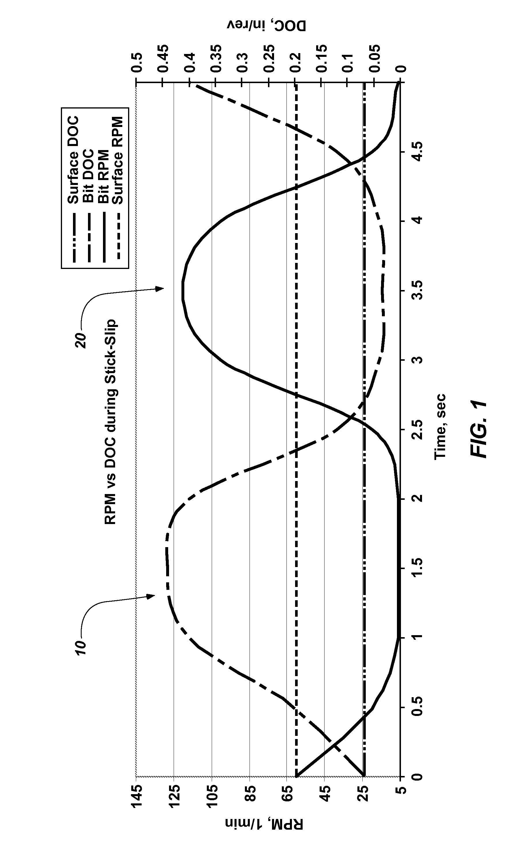
During drilling, fixed-cutter drill bits sometimes momentarily stick at the bottom of the wellbore, which results in rapidly increasing torque on the bit.
Once the torque on the bit reaches a threshold level, the bit will slip back into rotation resulting in a decrease in the torque on the bit.
The bit can oscillate between such sticking and slipping at a relatively high frequency, and such oscillation may be manifested in the form of vibrations in the drill string.
Stick-slip has been identified in the art as a primary cause of bit damage.
Data with diagnosis based on down-hole measurements in a controlled environment has been relatively limited.
Consequently, conflicting opinions continue to exist about the validity of the various theories set forth in the art for mitigation of stick-slip.
Drilling vibrations have been actively pursued by researchers for a long time as they can result in the failure of bits and BHA components and lead to increased drilling costs due to non-productive time (NPT) and reduced efficiency.
As shown in FIG. 2, low WOB and high RPM may result in bit whirl, while higher WOB and lower RPM may result in torsional instability that matures into stick-slip vibrations.

Method used


Image

  • Drill bit design for mitigation of stick slip
  • Drill bit design for mitigation of stick slip
  • Drill bit design for mitigation of stick slip

Examples


embodiment 1

[0050] A method of designing an earth-boring rotary drill bit, comprising: selecting a number of blades for a bit body of the drill bit; selecting cutting elements to be mounted to the bit body of the drill bit along a cutting element profile; identifying an intended median depth-of-cut for the drill bit during drilling; designing the cutting element profile and the bit body such that an expected average rubbing area between the bit body and a subterranean formation to be drilled by the drill bit increases to a value over zero at a depth-of-cut that is about one hundred and fifty percent (150%) or less of the intended median depth-of-cut, and such that the expected average rubbing area increases with increasing depth-of-cut at an average rate of at least three square inches per inch per revolution of the drill bit (3.0 in.2 / (in. / rev)) as the depth-of-cut increases from the intended median depth-of-cut for the drill bit to about two hundred percent (200%) of the intended median depth...

embodiment 2

[0051] The method of Embodiment 1, further comprising designing the cutting element profile and the bit body such that an expected average rubbing area between the bit body and a subterranean formation to be drilled by the drill bit is at least substantially zero at depths-of-cut equal to and below the intended median depth-of-cut.

[0052]Embodiment 3: The method of Embodiment 1 or Embodiment 2, further comprising designing the cutting element profile and the bit body such that the expected average rubbing area increases to a value over zero at a depth-of-cut that is about one hundred and thirty percent (130%) or less of the intended median depth-of-cut.

embodiment 4

[0053] The method of any one of Embodiments 1 through 3, further comprising designing the cutting element profile and the bit body such that the expected average rubbing area increases to a value over zero at a depth-of-cut that is about one hundred and twenty percent (120%) or less of the intended median depth-of-cut.

[0054]Embodiment 5: The method of any one of Embodiments 1 through 4, further comprising designing the cutting element profile and the bit body such that the expected average rubbing area between the bit body and a subterranean formation to be drilled by the drill bit increases with increasing depth-of-cut at an average rate of at least four and one-half square inches per inch per revolution of the drill bit (4.5 in.2 / (in. / rev.)) as the depth-of-cut increases from the intended median depth-of-cut for the drill bit to about two hundred percent (200%) of the intended median depth-of-cut for the drill bit.

[0055]Embodiment 6: The method of any one of Embodiments 1 through ...


PUM


Abstract

A method of designing an earth-boring rotary drill bit includes designing a bit body and cutting elements of the drill bit such that features of the drill bit other than cutting elements engage and rub against a subterranean formation being drilled by the drill bit at depths-of-cut beyond, but close to, an intended median depth-of-cut, and such that the amount of rubbing area between such features and the formation increases at a relatively rapid rate as the depth-of-cut increases beyond the intended median depth-of-cut. Such methods may be employed to mitigate the occurrence of the “stick-slip” phenomenon during drilling. A method of fabricating a drill bit includes configuring a bit body and cutting elements in accordance with such a design. Earth-boring drill bits include a bit body and cutting elements so configured.

Description

CROSS-REFERENCE TO RELATED APPLICATION[0001]This application claims the benefit of U.S. Provisional Patent Application Ser. No. 61 / 541,657, filed Sep. 30, 2011, the disclosure of which is hereby incorporated herein in its entirety by this reference.TECHNICAL FIELD[0002]Embodiments of the present disclosure relate generally to fixed-cutter earth-boring rotary drill bits, and to methods of designing, making, and using such fixed-cutter earth-boring rotary drill bits.BACKGROUND[0003]Earth-boring tools for forming wellbores in subterranean earth formations may include a plurality of cutting elements secured to a body. For example, fixed-cutter earth-boring rotary drill bits (also referred to as “drag bits”) include a plurality of cutting elements that are fixedly attached to a bit body of the drill bit.[0004]The cutting elements used in such earth-boring tools often include polycrystalline diamond compact cutters (often referred to as “PDCs”), which are cutting elements that include a p...

Claims


Application Information

Patent Timeline
Patent Type & Authority Patents(United States)
IPC IPC(8): E21B10/00E21B10/42G06F17/50
CPCE21B10/00G06F17/5086E21B10/42G06F30/17
Inventor SCHWEFE, THORSTENOUESLATI, HATEMLEDGERWOOD, III, LEROY W.JAIN, JAYESH R.FUSELIER, DANIELLE M.
Owner BAKER HUGHES INC
Learn More