
Microwave-based glass laminate fabrication

a technology of glass laminates and microwaves, applied in glass tempering apparatuses, electric/magnetic/electromagnetic heating, glass rolling apparatuses, etc., can solve the problems of non-selective approaches, glass layers suitable for laminate fusion can exhibit significant differences in their respective dielectric losses, and achieve the effect of reducing center tension, minimizing thickness variations, and improving edge finishing of glass laminates

Inactive Publication Date: 2015-07-28
CORNING INC
View PDF44 Cites 3 Cited by
  • Summary
  • Abstract
  • Description
  • Claims
  • Application Information

AI Technical Summary

Benefits of technology

This approach minimizes thickness variations, optimizes edge finishing, and facilitates the formation of complex 3D shapes by selectively heating target layers, reducing center tension and mitigating fracture risks during cutting, while maintaining a desired temperature profile across the laminate sheet.

Problems solved by technology

These outer-to-inner, non-selective approaches are typically only able to change the temperature and viscosity of the outer glass layer efficiently and cannot address the specific requirements specific to forming, cutting, finishing, tempering, and reshaping the laminate.
For example, in some embodiments, glass layers that are suitable for laminate fusion can exhibit significant differences between their respective dielectric losses.

Method used


Image

  • Microwave-based glass laminate fabrication
  • Microwave-based glass laminate fabrication
  • Microwave-based glass laminate fabrication

Examples


Embodiment Construction

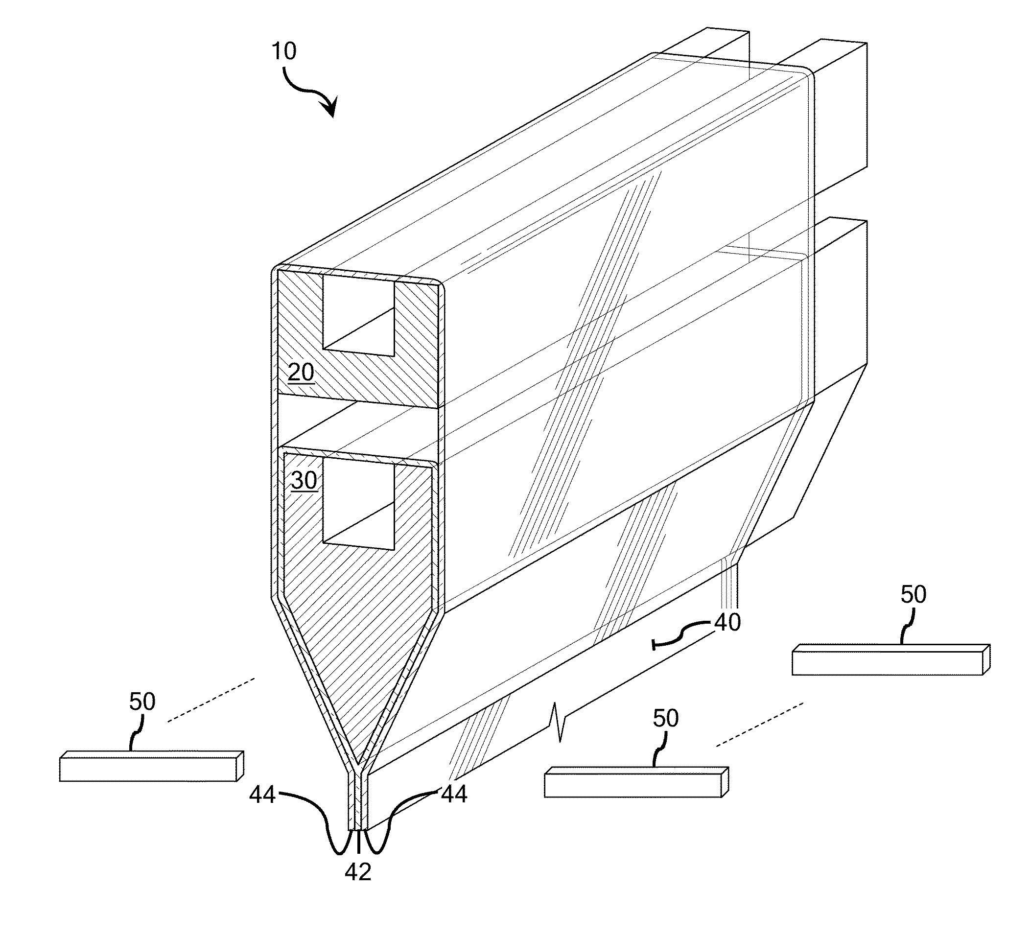
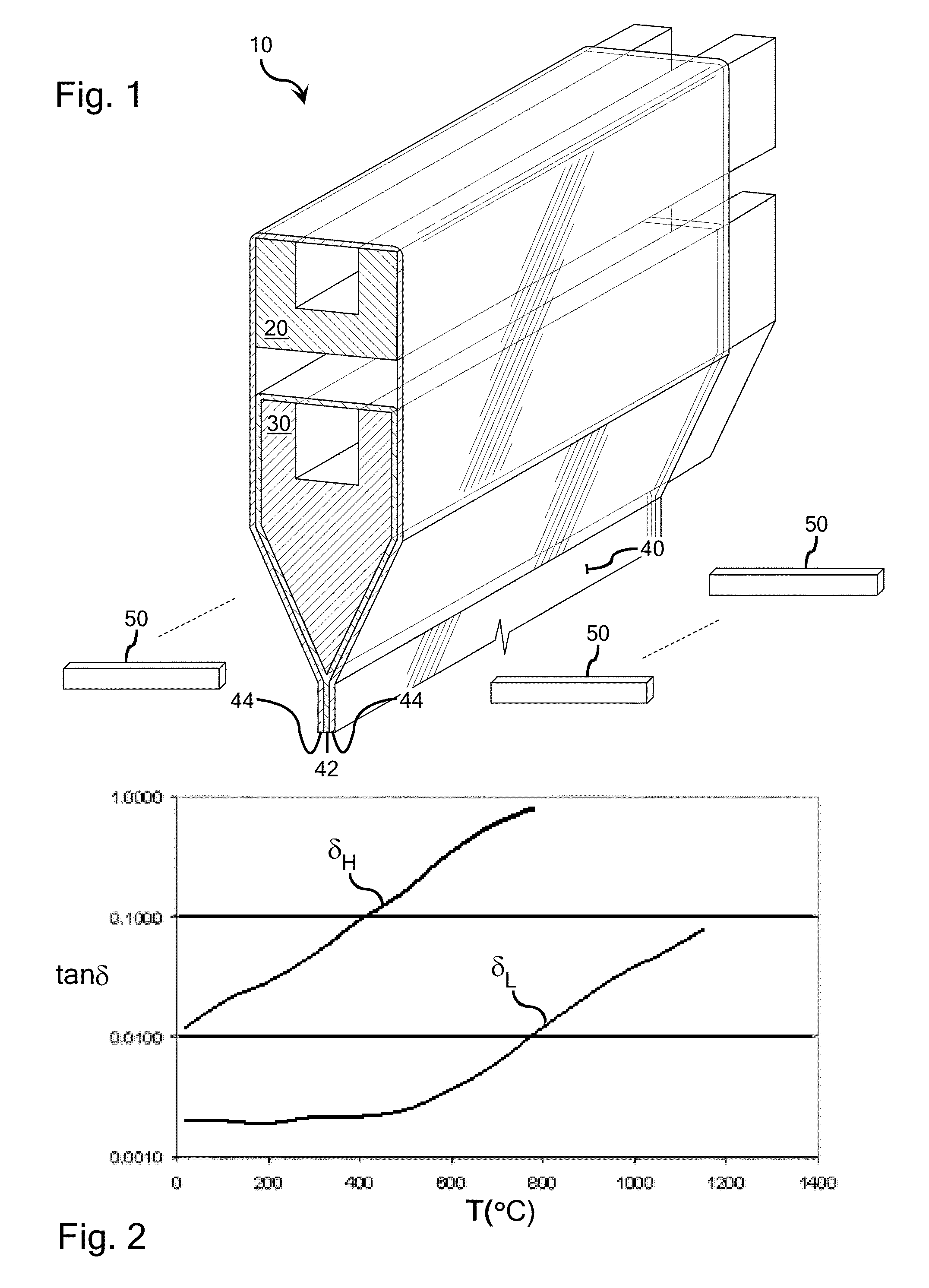
[0016]Methods of fabricating glass laminates in accordance with the teachings of the present disclosure can be conveniently illustrated with reference to the double isopipe fusion process illustrated schematically in FIG. 1, the details of which can be readily gleaned from available teachings in the art including, for example, Corning Incorporated U.S. Pat. Nos. 4,214,886, 7,207,193, 7,414,001, 7,430,880, 7,681,414, 7,685,840, 7,818,980, international publication WO 2004094321 A2, and PG Pub No. US 2009-0217705 A1.

[0017]As is illustrated in FIG. 1, in a laminate fusion process 10, molten outer layer glass overflows from an upper isopipe 20 and merges with the core glass at the weir level of a bottom isopipe 30. The two sides merge and a three-layer flat laminated sheet 40 comprising respective core and outer layers 42, 44 forms at the root of the core isopipe. The laminate sheet 40 can pass through several thermal zones for sheet shape and stress management and is then cut at the bo...


PUM

PropertyMeasurementUnit
viscosityaaaaaaaaaa
viscosityaaaaaaaaaa
temperatureaaaaaaaaaa

Abstract

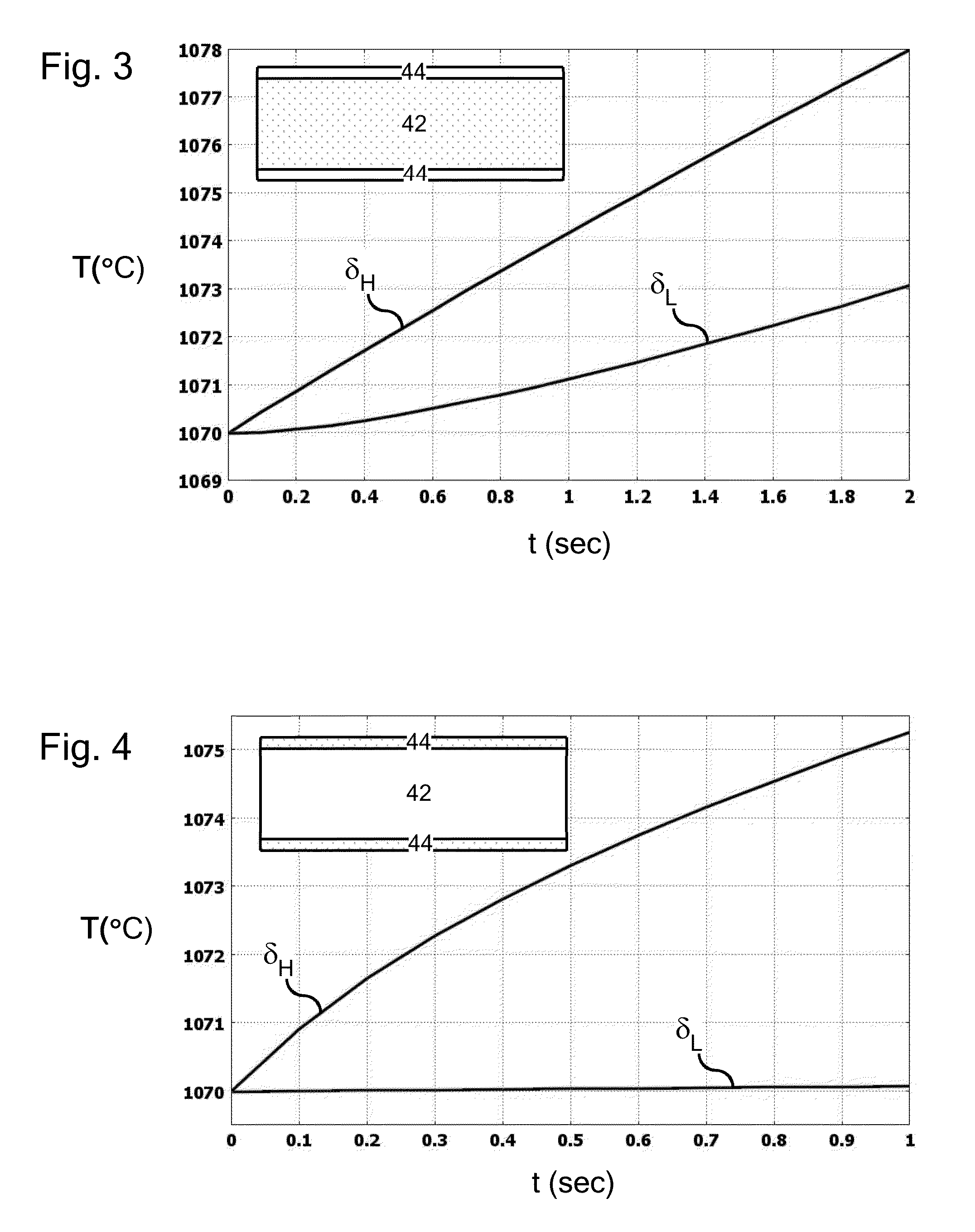
Methods of fabricating a glass laminate is provided. According to one embodiment, a glass laminate comprised of a microwave absorbing layer and a microwave transparent layer is formed. The microwave absorbing layer is characterized by a microwave loss tangent δH that is at least a half order of magnitude larger than a loss tangent δL of the microwave transparent layer. An area of the glass laminate is exposed to microwave radiation. The exposed area comprises a cross-laminate hot zone having a cross-laminate hot zone temperature profile. Substantially all microwave absorbing layer portions of the hot zone temperature profile and substantially all microwave transparent layer portions of the hot zone temperature profile reside above the glass transition temperature TG of the various layers of the glass laminate prior to impingement by the microwave radiation. In accordance with another embodiment, a method of fabricating a glass laminate is provided where the exposed area of the glass laminate is characterized by a viscosity below approximately 1×10⁴ poize.

Description

BACKGROUND[0001]1. Field[0002]The present disclosure relates to the fabrication of glass laminates.[0003]2. Technical Background[0004]Fabrication processes for glass laminates including laminated glass sheets, glass fibers, laminated rod and tube glass assemblies, and other glass lamintes typically require significant thermal control. Active control of viscosity, thermal stress and other thermal properties in these fabrication processes can be difficult.BRIEF SUMMARY[0005]The present inventors have recognized that traditional thermal approaches employed in the fabrication of glass laminates generally heat or cool from the outer layer of the laminate to the inner core layer of the laminate. This type of heating is non-selective with respect to the thermal properties of the various glass compositions of the laminate, which could for example comprise glass compositions with significantly different microwave absorption characteristics. These outer-to-inner, non-selective approaches are ...

Claims


Application Information

Patent Timeline
Patent Type & Authority Patents(United States)
IPC IPC(8): B32B17/00C03B13/10C03C23/00C03B17/00C03B17/02C03B23/023C03B17/06C03B18/12
CPCC03C23/0065C03B13/10C03B17/02C03B17/067C03B18/12C03B23/023B32B37/06C03B23/203C03B17/064C03B23/0235C03B27/012
Inventor GODARD, HILARY TONYPENG, GAOZHUPETERSON, IRENE MONASCHULZ, REBECCA LYNNSQUIER, GARY GRAHAM
Owner CORNING INC
Learn More