
Resonator silencer for a radial flow machine, in particular for a radial compressor

a radial compressor and resonance silencer technology, which is applied in the direction of machines/engines, stators, liquid fuel engines, etc., can solve the problems of vibration and structure-relevant malfunctions, damage to pipelines, and relatively high sound emissions or noise levels of radial compressors, and achieves the effect of simple installation and simple implementation

Inactive Publication Date: 2015-07-21
SIEMENS AG
View PDF34 Cites 9 Cited by
  • Summary
  • Abstract
  • Description
  • Claims
  • Application Information

AI Technical Summary

Benefits of technology

[0029]The invention is based on the object of specifying a silencer which improves the disadvantages from the prior art, is simple to implement and is also simple to install—in a sound-emitting system or device such as a radial turbomachine—and which is suitable in particular for damping sound emissions in the case of a radial compressor or a radial turbine.

Problems solved by technology

It is also known that such radial compressors exhibit relatively high sound emissions or noise levels which constitute a (noise) disturbance in the surroundings of the radial compressor.
Said sound emissions may furthermore also cause vibrations and structure-relevant malfunctions.
Here, in addition to the said noise disturbances, vibrations and structure-relevant malfunctions, pipeline vibrations may also occur which may lead to damage to the pipelines to the point of failure of the radial compressor or of the superordinate system that has the radial compressor.
The damping of such complex, transient, three-dimensional, rotating and / or pulsating pressure fields or sound fields is technically difficult.
Said noise reduction techniques may be relatively expensive, in particular if they are marketed as an “aftermarket” add-on product.
Absorption silencers have the disadvantage that they are generally unsuitable for high pressures, because—owing to the high pressures—large amounts of energy act on the absorption material, or large amounts of heat must be absorbed by the absorption material, which can lead to damage to the porous material, such as for example a disintegration of the absorption material.
In radial turbines, too, the described emission problems arise in a corresponding manner.

Method used


Image

  • Resonator silencer for a radial flow machine, in particular for a radial compressor
  • Resonator silencer for a radial flow machine, in particular for a radial compressor
  • Resonator silencer for a radial flow machine, in particular for a radial compressor

Examples


Embodiment Construction

[0066]Exemplary embodiments: resonator silencer for a radial compressor

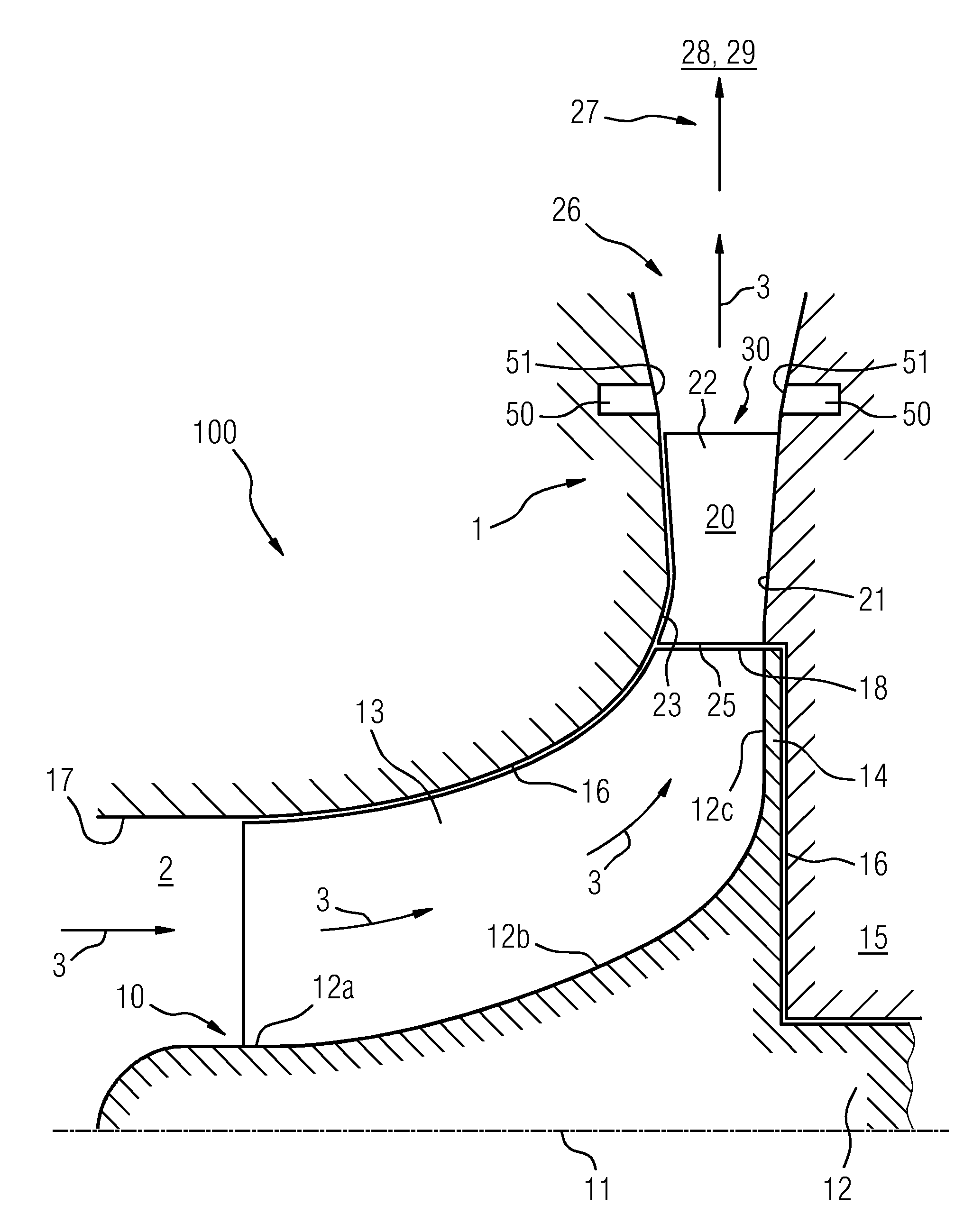
[0067]FIGS. 1 to 3 illustrate various configurations of radial compressors 100 each with a resonator silencer 1 realized or integrated in the diffuser.

[0068]Such radial compressors 100 have, as illustrated, a rotor 10 which rotates at high rotational speed about an axis 11. The rotor 10 has a hub 12 and blades 13 that project radially from said hub.

[0069]The hub 12 has a first region 12a which is substantially cylindrical, a transition region 12b in which the hub radius widens, and an end region 12c which runs substantially perpendicular to the axis 11.

[0070]The gas 2 that flows in axially in the flow direction 3 is set in rotation by the rotor 10 and exits the rotor 10 in the radial flow direction 3 with respect to the axis 11 and at an obtuse angle with respect to the axis 11.

[0071]The blades 13 are fastened to a common backplate 14 of the hub 12. The rotor 10 is situated in a housing 15, the wall 16 of which i...


PUM


Abstract

A volute for a radial turbomachine is proposed. The turbomachine includes a radial compressor or a radial turbine. The volute is in particular for a radial compressor. The volute has a substantially annular cavity which is delimited at least by a first radial side surface. At least one substantially annularly circumferential groove is formed in the side surface.

Description

CROSS REFERENCE TO RELATED APPLICATIONS[0001]This application is the US National Stage of International Application No. PCT / EP2012 / 052160 filed Feb. 9, 2012 and claims benefit thereof, the entire content of which is hereby incorporated herein by reference. The International Application claims priority to the German application No. 10 2011 005 025.6 DE filed Mar. 3, 2011, the entire contents of which is hereby incorporated herein by reference.FIELD OF INVENTION[0002]The invention relates to a diffuser for a radial compressor, which diffuser has a substantially annular hollow chamber which is delimited at least by a first radial side surface.BACKGROUND OF INVENTION[0003]Radial compressors are known for example from EP 1 356 168 B1 or from EP 1 602 810 A1.[0004]Such radial compressors are composed of a rotor or vane impeller which forms a compressor stage and which rotates about an axis of rotation and which has—with respect to the axis of rotation of the rotor—an axial inlet and a rad...

Claims


Application Information

Patent Timeline
Patent Type & Authority Patents(United States)
IPC IPC(8): B64F1/26F04D29/44F01D9/02F04D29/42F01D1/06F01N1/02F04D29/66B64F1/00F01N1/00F04D29/00
CPCF01N1/02F01D1/06F01D9/02F04D29/4206F04D29/444F04D29/665F05D2260/96F05D2250/52
Inventor KONIG, SVEN
Owner SIEMENS AG
Learn More