
Inkjet apparatus and method of collecting mist

a technology of inkjet equipment and mist collection, which is applied in the direction of printing, other printing equipment, etc., can solve the problems of reducing the lifetime of components and the danger of contact failure of connectors

Active Publication Date: 2015-07-14
DAINIPPON SCREEN MTG CO LTD
View PDF5 Cites 2 Cited by
  • Summary
  • Abstract
  • Description
  • Claims
  • Application Information

AI Technical Summary

Benefits of technology

[0008]It is therefore an object of the present invention to provide an inkjet apparatus and a mist collection method which are capable of collecting ink mist contained in a viscous flow moving near a surface of a base material without the use of an air knife.
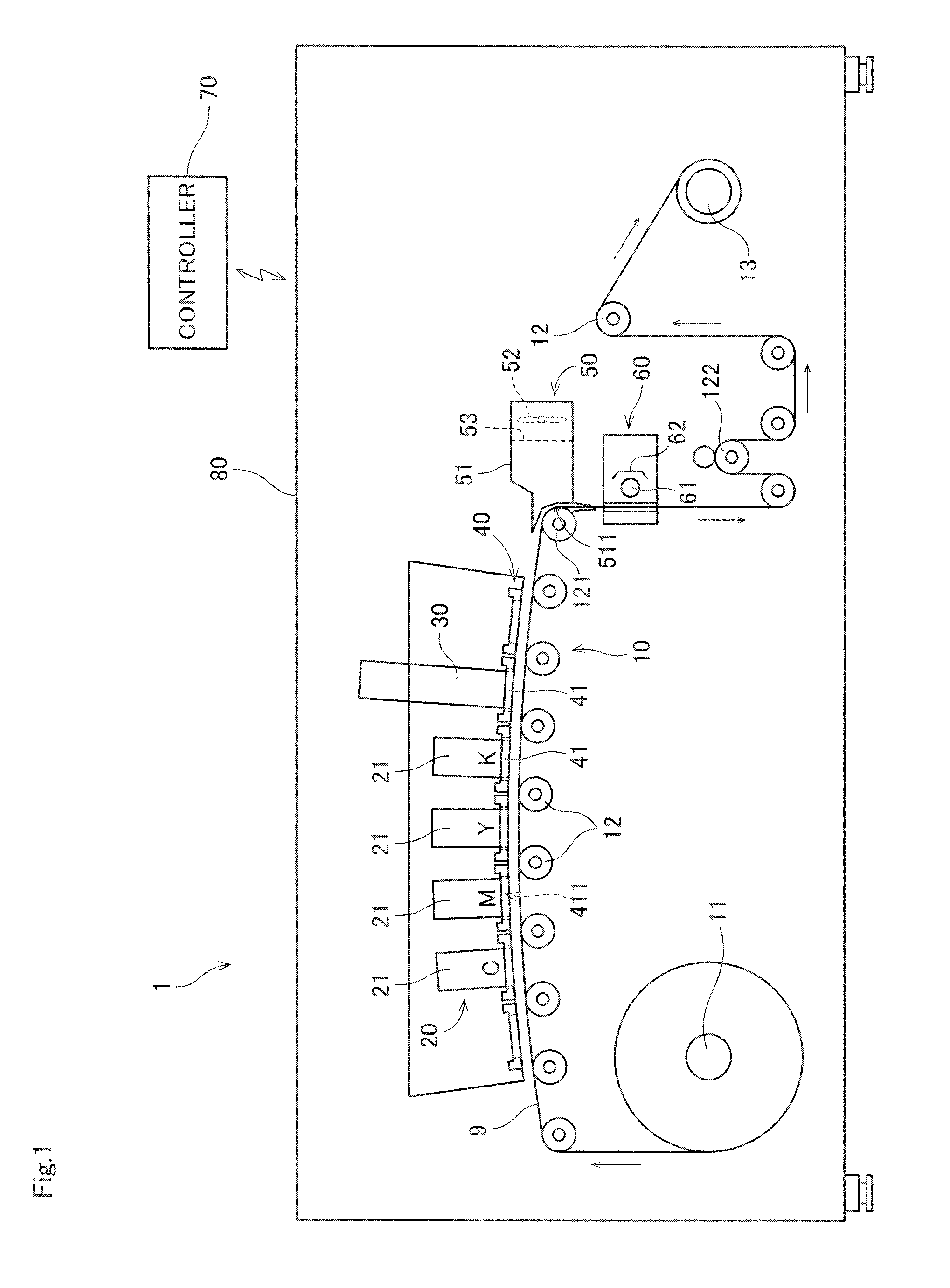
[0010]According to the first aspect of the present invention, the switching part switches the direction of movement of the base material to the direction opposite to the recording surface. Thus, a viscous flow and the ink mist contained in the viscous flow are separated from the recording surface of the base material by the use of inertial force. This allows the mist suction part to efficiently suction the separated ink mist.
[0012]According to the second aspect of the present invention, the direction of movement of the base material is switched to the direction opposite to the recording surface in the step a). Thus, a viscous flow and the ink mist contained in the viscous flow are separated from the recording surface of the base material by the use of inertial force. This allows the efficient suction of the separated ink mist in the step b).

Problems solved by technology

If diffused in an enclosure of the inkjet apparatus, the ink mist adheres to electronic components, mechanical components and the like in the enclosure to result in the danger of a contact failure of connectors and the reduction in lifetime of components.
Unfortunately, when a strip-shaped base material is transported, an airflow referred to as a viscous flow is produced near the surface of the base material.
It has hence been difficult for the structures disclosed in Japanese Patent Application Laid-Open No. 2010-201873 and Japanese Patent Application Laid-Open No. 2013-119218 to sufficiently collect the ink mist contained in the viscous flow.

Method used


Image

  • Inkjet apparatus and method of collecting mist
  • Inkjet apparatus and method of collecting mist
  • Inkjet apparatus and method of collecting mist

Examples


Embodiment Construction

[0019]A preferred embodiment according to the present invention will now be described with reference to the drawings.

[0020]

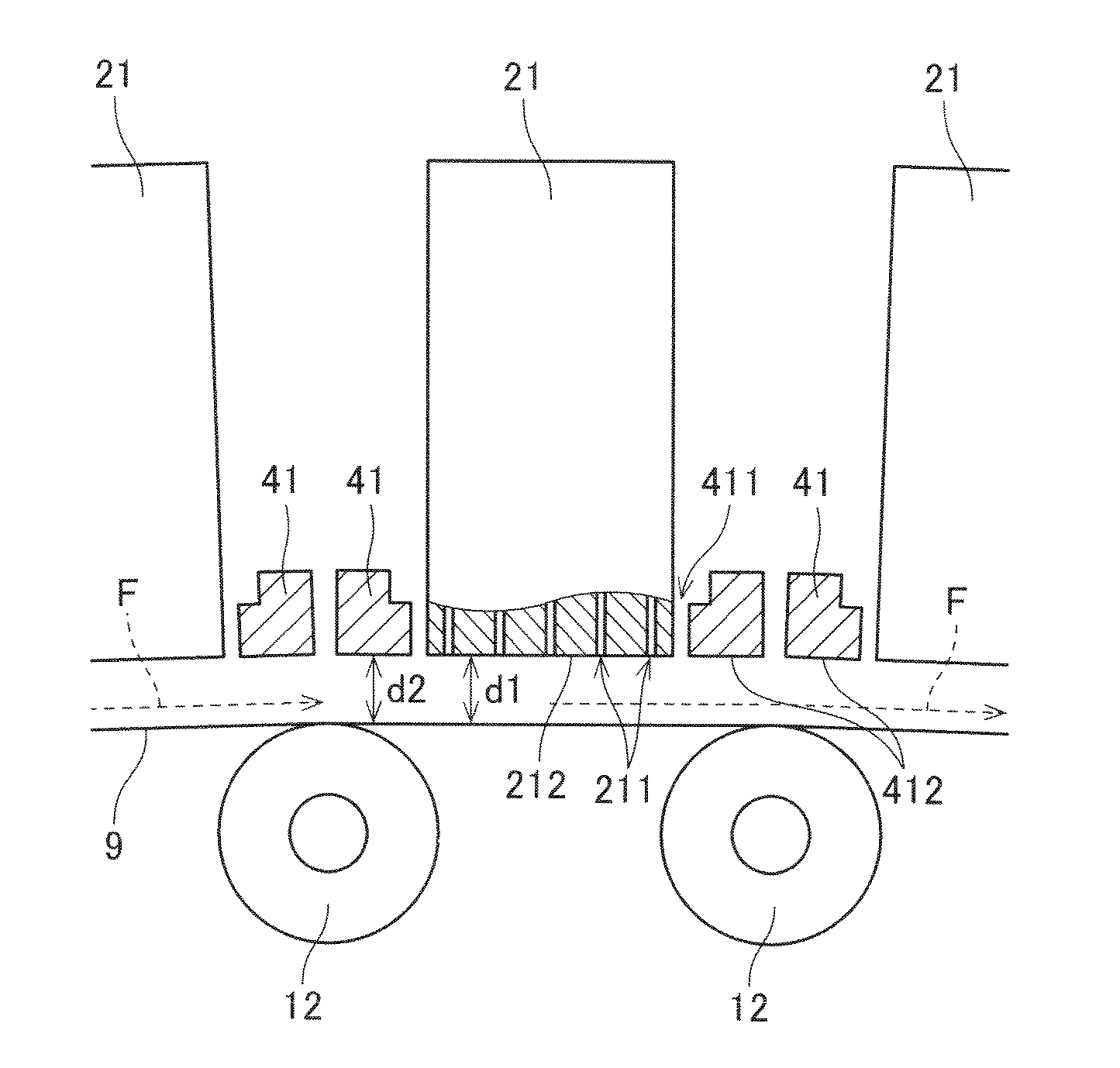
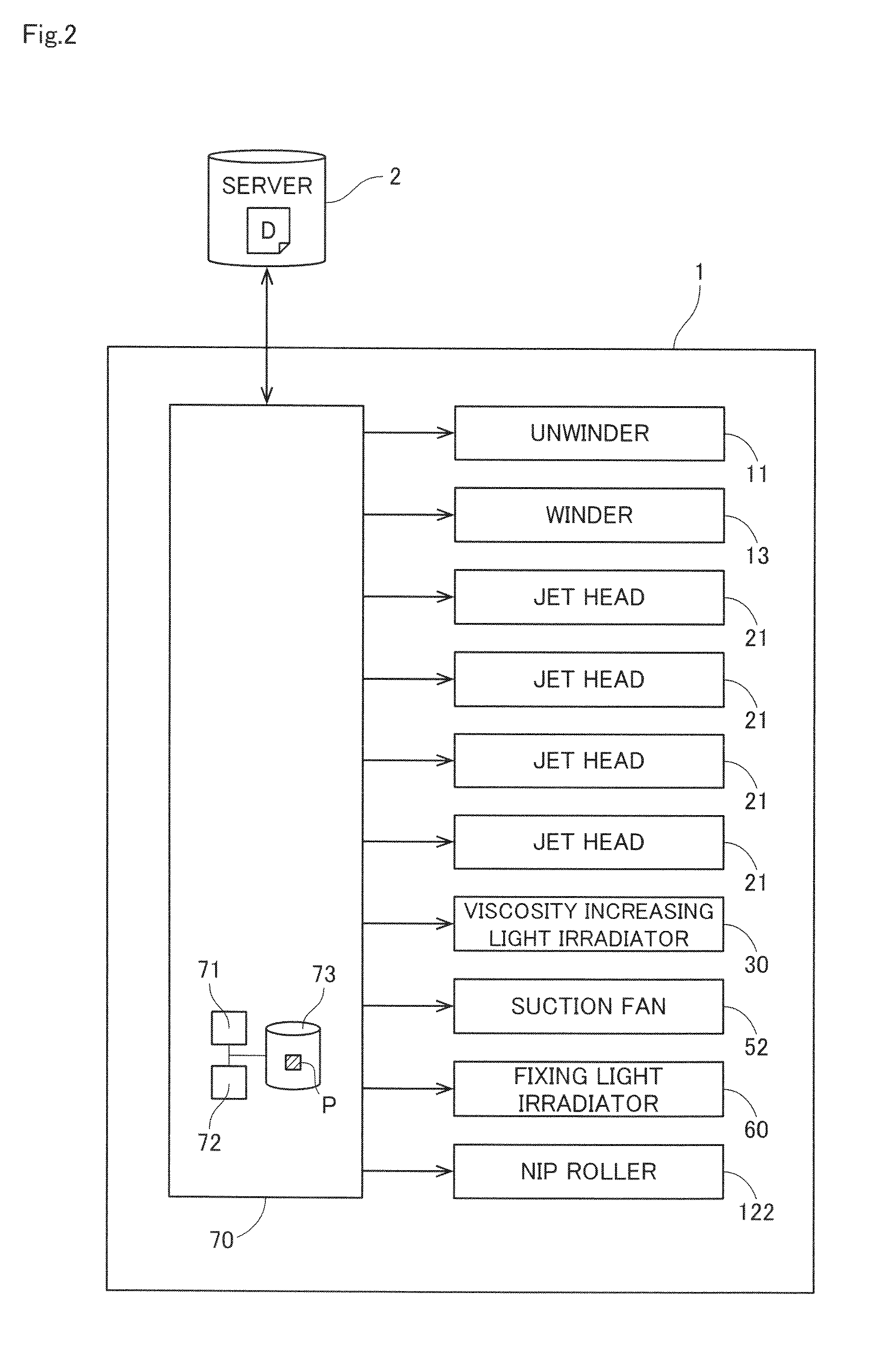
[0021]FIG. 1 is a view showing the configuration of an inkjet apparatus 1 according to one preferred embodiment of the present invention. This inkjet apparatus 1 is a printing apparatus which records a color image on a recording surface of printing paper 9 that is a strip-shaped base material by jetting out ink droplets from a plurality of jet heads 21 while transporting the printing paper 9. As shown in FIG. 1, the inkjet apparatus 1 according to the present preferred embodiment includes a transport mechanism 10, an image recorder 20, a viscosity increasing light irradiator 30, a support unit 40, a mist suction part 50, a fixing light irradiator 60, and a controller 70. The components except the controller 70 are housed in a box-like processing chamber 80.

[0022]The transport mechanism 10 is a mechanism for transporting the printing paper 9 in a direction of mov...


PUM


Abstract

An inkjet apparatus includes a switching part for switching the direction of movement of a base material, and a mist suction part for suctioning air containing ink mist. The switching part bends the base material in a direction opposite to a recording surface of the base material in a position downstream in the direction of movement as viewed from jet heads to switch the direction of movement from a first direction to a second direction. Thus, a viscous flow near the surface of the base material and the ink mist contained in the viscous flow are separated from the surface of the base material by the use of inertial force. The mist suction part includes a suction opening at least part of which is positioned on the extension of the first direction. This allows the mist suction part to efficiently suction the ink mist separated from the surface of the base material.

Description

BACKGROUND OF THE INVENTION[0001]1. Field of the Invention[0002]The present invention relates to a technique for collecting ink mist in an inkjet apparatus which jets out ink droplets toward a recording surface of a strip-shaped base material while transporting the base material.[0003]2. Description of the Background Art[0004]An inkjet apparatus which records an image on a surface of a strip-shaped base material by jetting out ink from a plurality of heads while transporting the base material has heretofore been known. When the inkjet apparatus of this type jets out ink from the heads, fine ink mist is produced. If diffused in an enclosure of the inkjet apparatus, the ink mist adheres to electronic components, mechanical components and the like in the enclosure to result in the danger of a contact failure of connectors and the reduction in lifetime of components. To solve such a problem, a variety of techniques have heretofore been proposed to collect ink mist by suction.[0005]For e...

Claims


Application Information

Patent Timeline
Patent Type & Authority Patents(United States)
IPC IPC(8): B41J2/15B41J2/165
CPCB41J2/16532B41J2/1714B41J29/17
Inventor IWASA, HIROSHI
Owner DAINIPPON SCREEN MTG CO LTD
Learn More