
Automatic thruster control of a marine vessel during sport fishing mode

a technology of automatic control and marine vessels, applied in vessel auxiliaries, steering initiations, instruments, etc., can solve the problems of difficult maneuvering, difficult mastery of maneuvering methods, and high cost of operation

Inactive Publication Date: 2015-06-30
TWIN DISC
View PDF22 Cites 14 Cited by
  • Summary
  • Abstract
  • Description
  • Claims
  • Application Information

AI Technical Summary

Benefits of technology

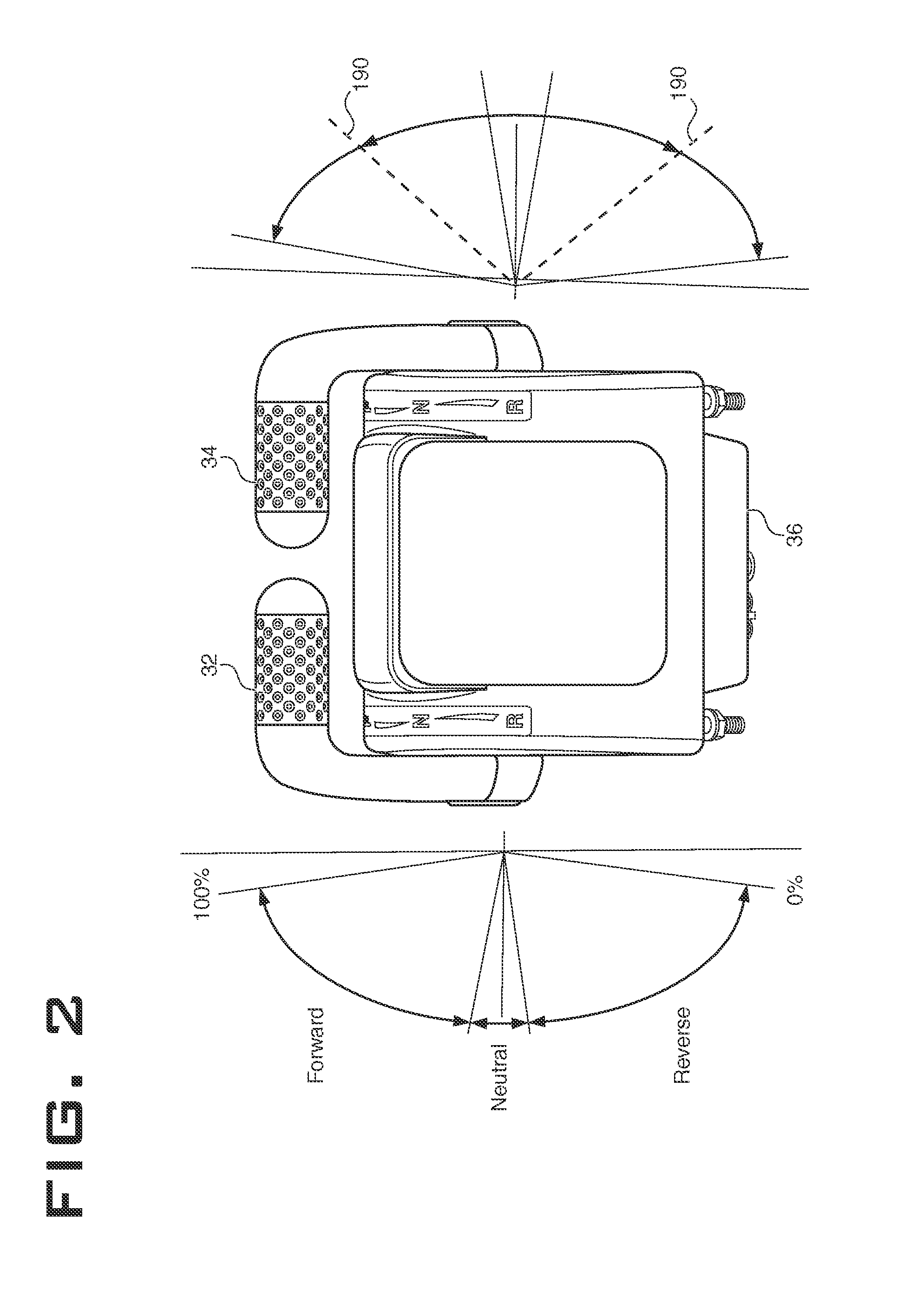
This patent describes a marine vessel with a system that receives signals from control levers and activates a thrusting mechanism to produce turning moments in the vessel. The system is designed to produce a clockwise turning moment if the signal from the left lever is greater than the signal from the right lever, and a counter-clockwise turning moment if the signal from the right lever is greater than the signal from the left lever. The technical effect of this design is improved control and efficiency in turning the marine vessel.

Problems solved by technology

When the angler has hooked a substantial fish, it can take a significant amount of effort by the entire crew to catch and bring aboard the fish.
This manner of maneuvering is hard to master and requires a skilled operator.
Therefore, the operator cannot operate both the Palm Beach levers and the bow / stern thrusters at the same time.
Examples such as Ashby et al use a bow thruster for maneuvering the vessel, but are limited to low engine speeds and are not suitable for sport fishing.
For instance, such a system is disclosed in United States Publication No. 2009 / 0197486, to Szilagyi et al., dated Aug. 6, 2009, entitled “Method and system for maneuvering aquatic vessels.” The example disclosed in Szalagyi et al provides for a sport fishing mode that uses high engine speed and high power, but cannot provide the additional maneuverability of bow or stern thrusters.

Method used


Image

  • Automatic thruster control of a marine vessel during sport fishing mode
  • Automatic thruster control of a marine vessel during sport fishing mode
  • Automatic thruster control of a marine vessel during sport fishing mode

Examples


Embodiment Construction

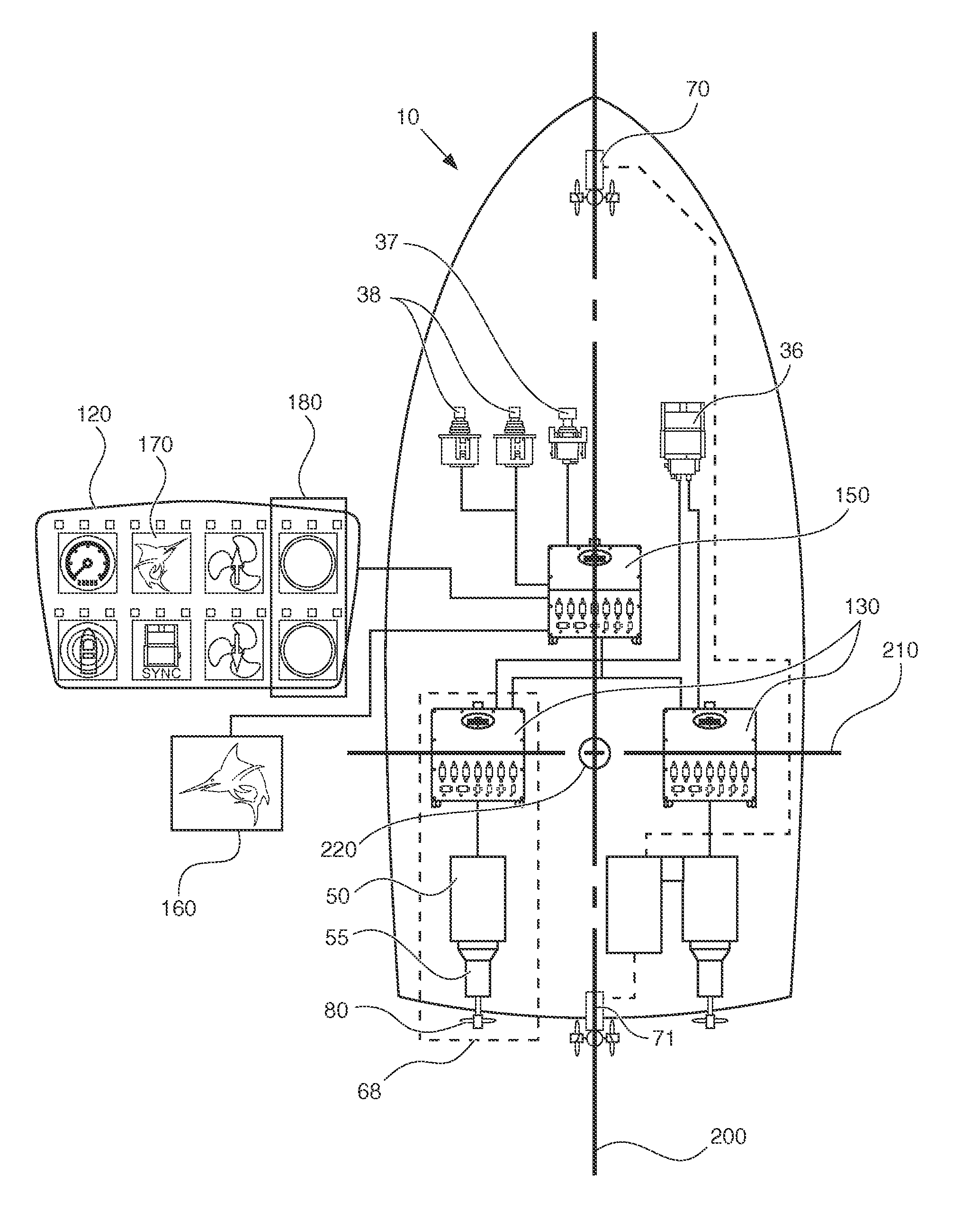
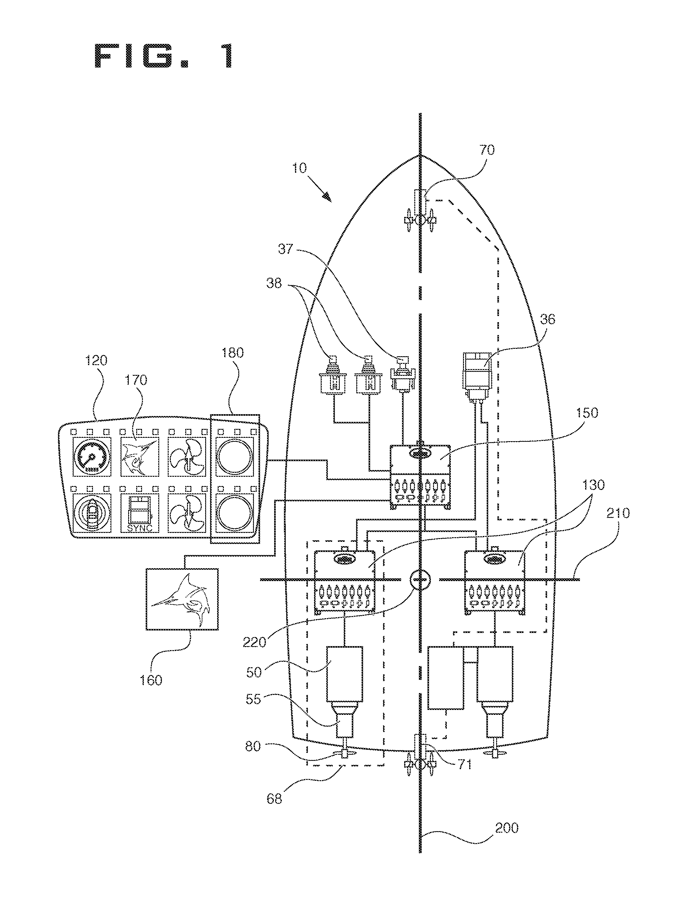
[0012]FIG. 1 shows the major mechanical components of a marine vessel 10 according to the present disclosure. The marine vessel 10 includes an operator's station 35 where the major controls of the vessel are located. Such controls include control levers 36, a joystick 37, thruster controls 38, a keypad 120, and a display 160. The controls may be connected via a control area network (CAN) 155. The CAN is of the type that is commonly known in the art, such as J1939. Some or all of the controls may also be located at redundant locations such as a fly bridge 40 or a remote operator's station 45.

[0013]The marine vessel 10 includes at least one propulsion unit 68. The propulsion unit 68 includes, at least in part, an engine 50, a transmission 55, a propeller 80, and an electronic propulsion unit controller 130. The propulsion unit controller 130 may control both the engine 50 and transmission 55, or there may be separate propulsion unit controllers 130 for the engine 50 and transmission 5...


PUM


Abstract

A marine vessel is disclosed having a control system for automatically controlling thrusters for steering the marine vessel for the purpose of aiding an angler who has hooked a fish. The control system will automatically control the thrusters based on the positions of the propulsion unit control levers if the control levers are split. The control system may also control the thrusters if the propulsion unit control levers have moved past a predetermined threshold. The predetermined threshold can be set by the operator of the marine vessel.

Description

TECHNICAL FIELD[0001]This disclosure relates to automatically controlling a marine vessel in sport fishing applications.[0002]Sport fishing often involves a fisherman, or “angler”, using a rod and reel to catch a fish. The angler often fishes from a marine vessel in order to reach a favorable fishing location. When the angler has hooked a substantial fish, it can take a significant amount of effort by the entire crew to catch and bring aboard the fish. The angler engages in a tug-of-war with the fish as it changes location relative to the marine vessel. The operator of the boat must then maneuver the stern of the vessel so that it is oriented toward the fish in order to aid the angler as the fish moves. Typically such a vessel is equipped with special levers, known as “Palm Beach levers”, for steering the vessel during sport fishing maneuvers. These levers are located at the operator's station and are designed to be manipulated by the operator who faces the stern of the vessel while...

Claims


Application Information

Patent Timeline
Patent Type & Authority Patents(United States)
IPC IPC(8): G05D1/08G05D1/00B63H25/46B63J3/02B63H25/42B63H21/21B63H5/14B63H25/02G05D1/02B63B39/08
CPCB63H25/42B63H25/46G05D1/00G05D1/0206G05D1/0875B63H21/21G05D1/0016B63H21/213B63B39/08G05D1/02G05D1/08Y02T70/127B63J3/02B63H2025/026B63B34/05Y02T70/10
Inventor YUET, FU P.MARZUQ, HASHIMCALLAGHAN, MERRITT P.LEE, PATRICKHUTCHISON, ANDREW
Owner TWIN DISC
Learn More