
Membrane-enabled reverse lung

a reverse lung and membrane technology, applied in the field of life support systems, can solve the problems of reducing the number of machines, reducing the size and weight of the system described above, and posing an explosion

Active Publication Date: 2015-06-30
OCEANEERING INTERNATIONAL
View PDF1 Cites 4 Cited by
  • Summary
  • Abstract
  • Description
  • Claims
  • Application Information

AI Technical Summary

Benefits of technology

The present invention is a device and process that integrates CO2 separation and concentration, and O2 generation by water electrolysis. It is designed to remove CO2, water vapor, and heat from air, and generate ambient-pressure gas streams of O2 and H2. The invention utilizes multi-fault-tolerant designs that do not require explosion-proof enclosures. The technical effects of the invention include improved air revitalization for crewed spacecraft and submarines, as well as in other sealed or potentially sealed environments such as nuclear, biological, chemical hardened bunkers or vehicles. The invention also includes a method for generating concentrated CO2 gas and a bicarbonate solution.

Problems solved by technology

Two technically challenging problems in crewed spacecraft and submarine life support are carbon dioxide (CO2) separation and concentration, and safe oxygen (O2) generation by water electrolysis.
A failure of the membrane would allow the O2 and H2 gasses to combine, leading to a possibility of explosion.
Because of the explosion potential inherent in a one-fault-tolerant water electrolysis system, and the consequent need for explosion-proof enclosures, systems of the kind described above are limited in size and weight.
Reduction of the number of machines saves space, while reduction in the number of moving parts increases overall reliability of the system due at least to failure of a moving part.
Furthermore, weight is very often a concern in the environments in which a water electrolysis system could be used.
Additionally, energy storage and generation are often limited in environments that make use of life support systems.

Method used


Image

  • Membrane-enabled reverse lung
  • Membrane-enabled reverse lung
  • Membrane-enabled reverse lung

Examples


Embodiment Construction

[0020]Reference will now be made in detail to the preferred embodiments of the present invention, examples of which are illustrated in the accompanying drawings. Wherever possible, the same reference numbers will be used throughout the drawings and description to refer to the same or like parts.

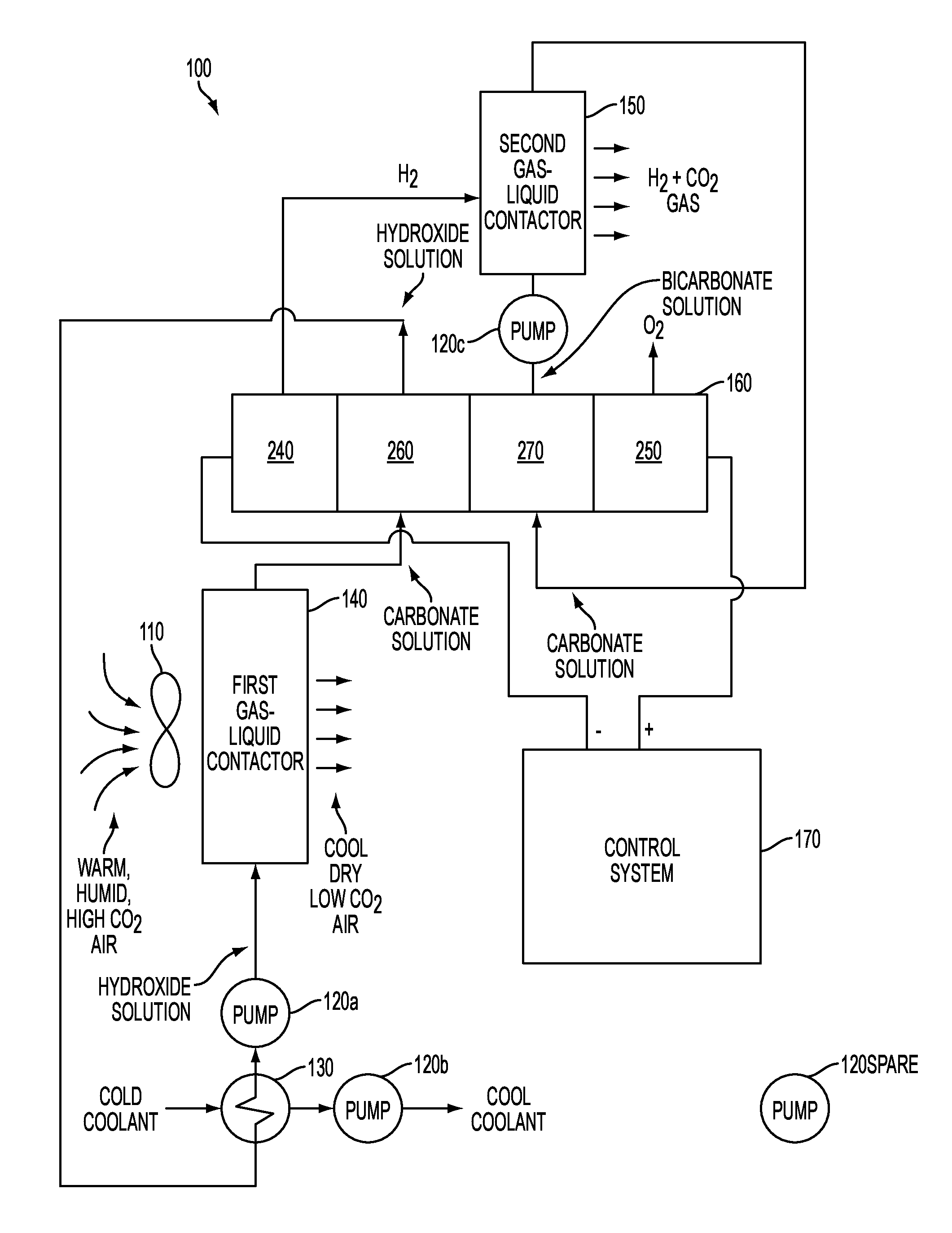
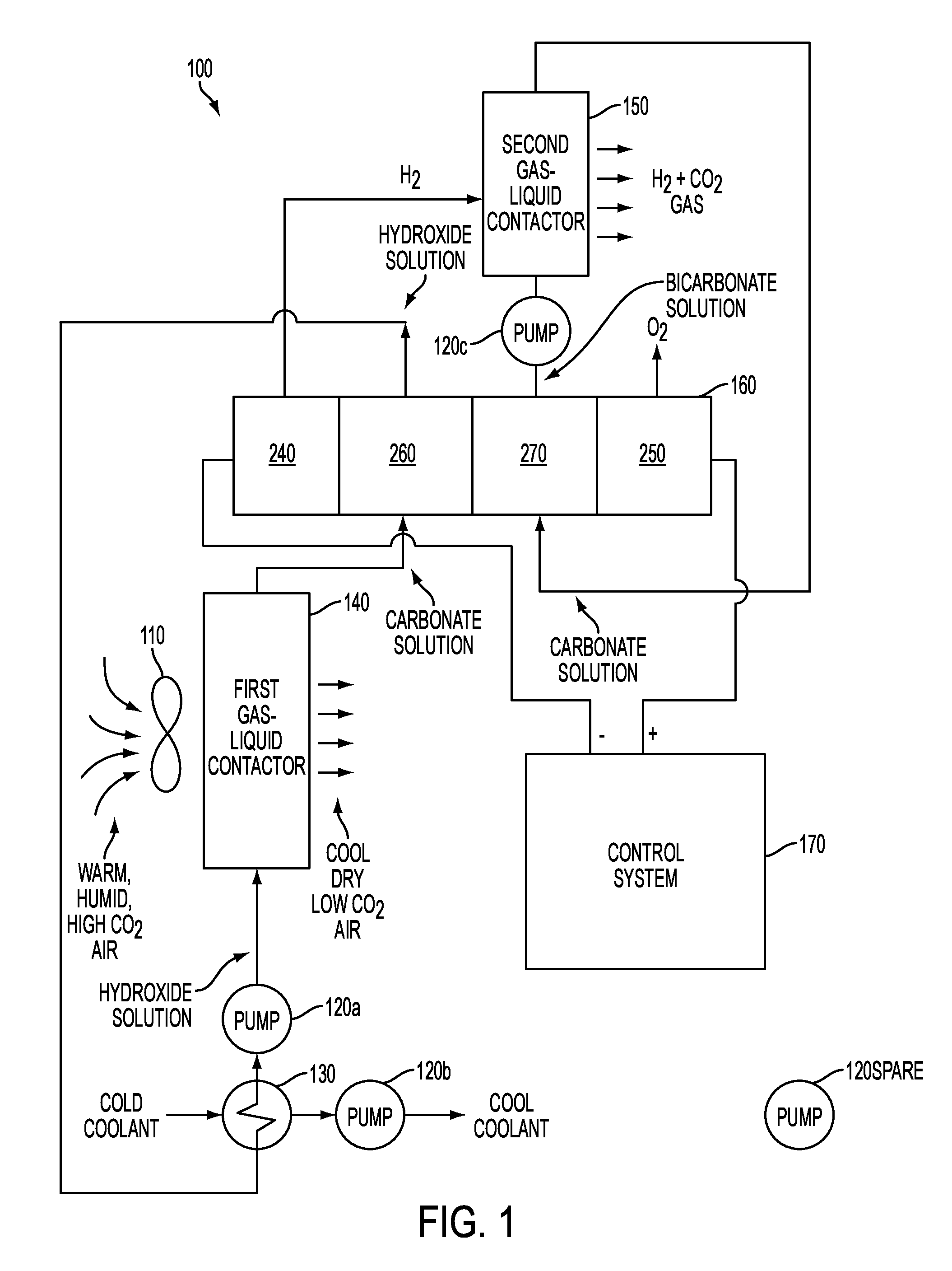
[0021]The life support (otherwise referred to as air revitalization or air purification) apparatus and methods claimed herein may be thought of as providing a reverse of the functionality of a human lung. The human lung removes O2 from air and puts CO2, water vapor (humidity), and heat into air; the apparatus and methods claimed herein remove CO2, water vapor, and heat from air, and put O2 into air. Therefore, for ease of reference and without any intent of limiting the claimed invention, each of the various embodiments of the apparatus described herein may be referred to as a Membrane-Enabled Reverse Lung (MERL).

[0022]Embodiments of the MERL described herein concentrate, by volume, CO2 by a ...


PUM

PropertyMeasurementUnit
water vapor pressureaaaaaaaaaa
temperatureaaaaaaaaaa
partial pressureaaaaaaaaaa

Abstract

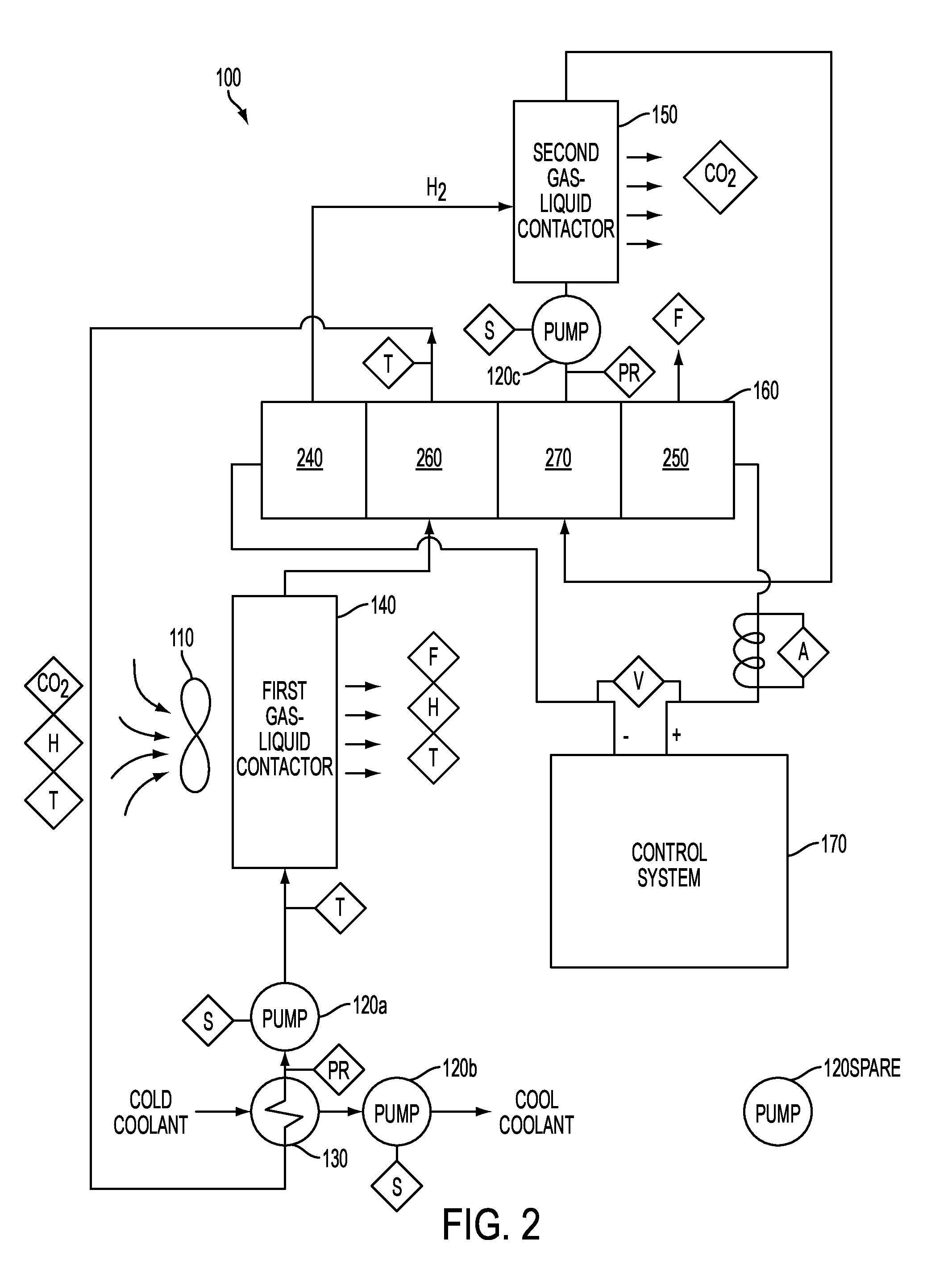
An air revitalization apparatus and method simultaneously removes carbon dioxide, water vapor, and heat from air and produces oxygen gas, hydrogen gas, and concentrated carbon dioxide gas, does not require an explosion proof enclosure, and includes a fan configured to blow air into a first gas-liquid contactor, an electrochemical cell including first through fourth passages configured to emit hydrogen gas, permit a flow of a carbonate-hydroxide solution, permit a flow of carbonate-bicarbonate solution, and emit oxygen gas, respectively, the first and fourth passages separated by at least three gas-impermeable membranes, and a second gas-liquid contactor, where the first gas-liquid contactor, second passage, and a first pump are configured to circulate the carbonate-hydroxide solution therethrough, where the second gas-liquid contactor, third passage, and a second pump are configured to circulate the carbonate-bicarbonate solution therethrough, and where the output of the first passage is operationally coupled to the second gas-liquid contactor.

Description

CROSS-REFERENCE TO RELATED APPLICATIONS[0001]This application claims the benefit of priority from U.S. Provisional Application No. 61 / 694,998, filed on Aug. 30, 2012, the content of which is incorporated by reference herein in its entirety.TECHNICAL FIELD[0002]The present invention relates to life support systems of the type found in space stations and submarines, but the present invention is not limited to operation in those locations. More particularly, the present invention relates to electrochemical cells used to purify air by reducing levels of CO2 and water vapor in the air and providing a flow of O2. The present invention is two-fault tolerant and is therefore inherently safe from explosions caused by the mixing of H2 and O2 gases that it generates. Accordingly, embodiments of the present invention are able to operate without being enclosed within explosion-proof enclosures.BACKGROUND OF THE INVENTION[0003]Two technically challenging problems in crewed spacecraft and submarin...

Claims


Application Information

Patent Timeline
Patent Type & Authority Patents(United States)
IPC IPC(8): A62B21/00C25B1/04C25B15/02C25B15/08C25B9/08A62B13/00C25B9/19
CPCA62B21/00C25B1/04A62B13/00C25B15/02C25B15/08C25B9/08Y02E60/366Y02E60/36C25B9/19
Inventor NOYES, GARY PATRICK
Owner OCEANEERING INTERNATIONAL
Learn More