Locating of pressure taps on face of orifice plate device

a technology of orifice plate and pressure tap, which is applied in the direction of measuring devices, volume/mass flow by dynamic fluid flow effect, instruments, etc., can solve the problems of increasing the susceptibility of performance errors of typical axially spaced pressure ports, and not being able to accurately indicate the rate of fluid flow

Active Publication Date: 2015-06-23
DIETERICH STANDARD
View PDF15 Cites 10 Cited by
  • Summary
  • Abstract
  • Description
  • Claims
  • Application Information

AI Technical Summary

Benefits of technology

[0010]Accordingly, an averaging orifice plate flow meter, such as Rosemount's Conditioning Orifice Plate, a flow impedance device having a plurality of variously positioned orifices, may be placed in a fluid-carrying conduit with static pressure measurement taken on the upstream and downstream sides of the plate. Each of the plurality of orifices will conduct a part of the total fluid flow within the conduit. According to Bernoulli's theorem, the velocity of the fluid through each of the orifices will increase, and the static fluid pressure on the downstream side of the constricting plate that is attributable to each of the separate orifices will be averaged within the fluid to provide an average downstream static pressure. The average downstream static pressure is compared with the upstream static pressure to provide an average differential pressure for whatever velocity profile is presented to the multiple orifice plate, resulting in an accurate measurement of the rate of fluid flow in the pipe.
[0012]Accordingly, the present invention incorporates at least one of the pressure taps into one of the respective faces of an averaging orifice plate, rather than spacing them some distance from either side of the plate. The incorporation of at least one of the pressure ports in this manner consists of at least one opening on at least one of the faces of the plate, upstream and / or downstream, connected by fluid communication channel(s) to respective pressure taps located on the circumferential edge of the plate, or alternatively, in the stem of the plate. These taps are then connected to a valve manifold and transmitter in the manner typical in the art to enable measurement of pressure differentials, ultimately used to calculate rate of fluid flow. Incorporation of at least one of the pressure taps into the face of the plate in this manner will minimize any adverse affect on the precision of the readings delivered by pressure taps even in disturbed conditions at higher beta ratios. An incorporated upstream port will allow measurement of the impact pressure at the face of the plate, thereby allowing measurement of higher differential pressures. The benefit will be better resolution of the pressure signal without additional pressure loss. An incorporated downstream port will allow measurement of the low static pressure in an area with high recirculation and mixing enabling a better averaging of downstream pressure despite flow disturbances. Alternate embodiments, wherein only one of the two pressure taps is incorporated into one of the respective faces of the plate and the other pressure tap is a tap of the type known in the art, such as a flange tap, would also realize some if not all of the aforementioned benefits.

Problems solved by technology

However, if the velocity profile is skewed, the differential pressure across the constricting plate will not be a true indication of the rate of fluid flow.
However, even when such ideally simplistic flow conditioning devices are utilized, instead of upstream flow straighteners, disturbances to the pressure measuring ports, which are typically placed on the pipe wall some distance upstream and some distance downstream of the conditioning orifice plate, may still result especially when utilized in conjunction with higher beta ratio orifice plates downstream of typical pipe flow disturbances.
Typical axially spaced pressure ports have an increased susceptibility to performance errors in such conditions.

Method used


Image

  • Locating of pressure taps on face of orifice plate device
  • Locating of pressure taps on face of orifice plate device
  • Locating of pressure taps on face of orifice plate device

Examples


Embodiment Construction

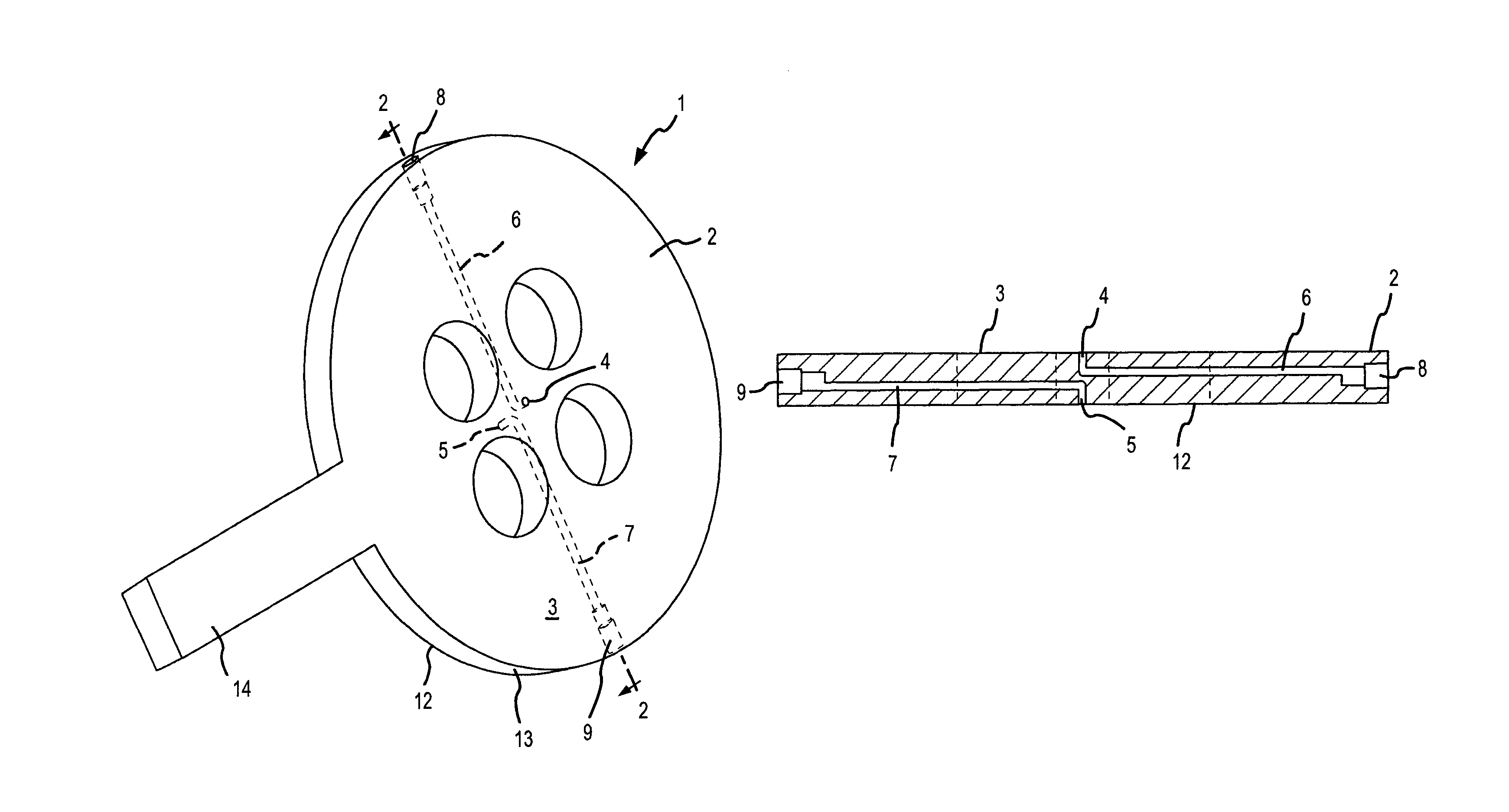
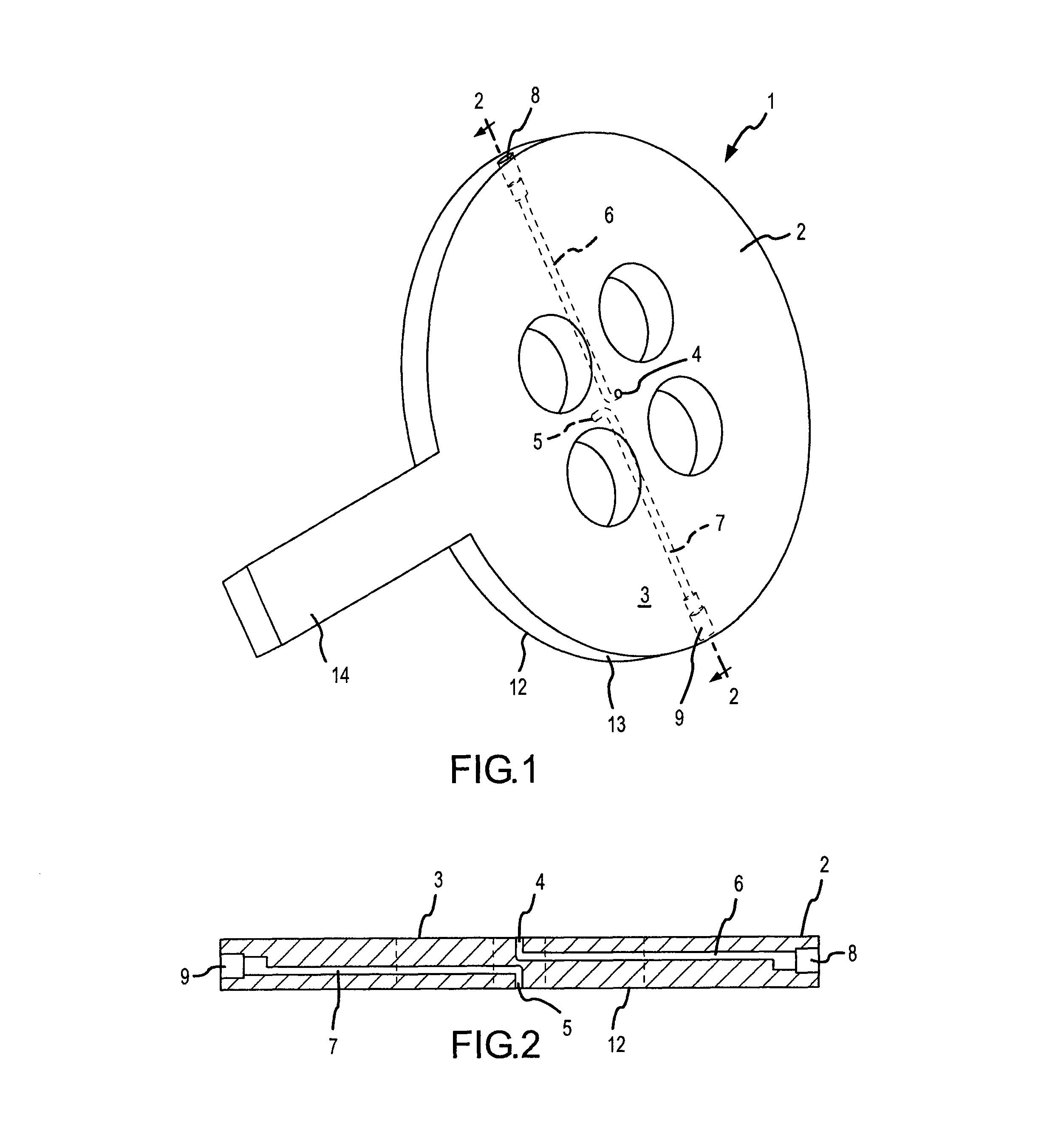
[0021]A simplified version of the present invention is shown in FIGS. 1 and 2. The averaging orifice plate flow element comprises a flat plate 1 having a circular portion 2 and a stem 14. On a diametric line across the circular portion there is disposed within the plate a first conduit or bore 6 that interconnects the opening 4 in the downstream face 3 of the circular portion 2 of the plate to a first pressure sensing port 8 disposed in the circumferential edge 13 of the circular portion 2 of the plate. A second conduit or bore 7 interconnects an opening 5 in the upstream face 12 of the plate to a second pressure sensing port 9 in the circumferential edge 13 of the circular portion 2. The pressure ports are arranged to be connected to a traditional fluid manifold (not shown) and into a pressure transducer (not shown). An electrical signal that represents the sensed differential pressure between the ports 8 and 9 is transmitted by transmitter (not shown) to a processing unit (not sho...


PUM


Abstract

A process flow device that includes a self-averaging orifice plate type of primary flow element with a high pressure tap located on or incorporated into its upstream surface, and a low pressure tap located on or incorporated into its downstream surface, for measuring, by a differential pressure process, the volumetric rate of fluid flow at a point in a fluid carrying conduit where the velocity profile of the fluid is asymmetric with respect to the longitudinal axis of the conduit. The improved pressure tap configuration consists of two fluid conduits, one carried by each of the downstream and upstream faces of the orifice plate, establishing fluid communication between openings in the downstream and upstream faces of the orifice plate and their respective terminal pressure ports. Location of the pressure taps on the faces of the orifice plate in this manner allows for increased resolution of the pressure signals by minimizing the effects of upstream pipe flow disturbances on pressure taps used in conjunction with conditioning orifice plate primary flow elements, especially those with higher beta ratios.

Description

FIELD OF THE INVENTION[0001]The present invention relates generally to a process flow device that includes a multiple aperture orifice plate type of primary flow element having at least one pressure tap located on its face in order to minimize disturbances in measuring, by a differential pressure process, the volumetric rate of fluid flow at a point in a fluid carrying conduit.BACKGROUND OF THE INVENTION[0002]Differential pressure process flow meters, long known in the art, measure the rate of flow of a liquid or gas by calculating the difference in pressure between a measurement taken at a high pressure tap upstream of a process flow device, and a low pressure tap downstream of the process flow device. When the primary flow element used is an orifice plate within a fluid carrying conduit such as a pipe, commonly used pressure tap types include: flange taps, corner taps, D & D / 2 taps, and pipe taps. Although the tap configuration and axial distances from the orifice plate differ, al...

Claims


Application Information

Patent Timeline
Patent Type & Authority Patents(United States)
IPC IPC(8): G01F1/46G01F1/32G01F1/42
CPCG01F1/42
Inventor IFFT, STEPHEN ARTHURORLESKIE, CHARLES THEODORE
Owner DIETERICH STANDARD
Why Eureka
Try Eureka