
Implantable lead with a band stop filter having a capacitor in parallel with an inductor embedded in a dielectric body

a dielectric body and inductor technology, applied in the direction of fixed capacitors, feed-through capacitors, therapy, etc., to achieve the effect of rapid imagery

Inactive Publication Date: 2015-06-23
WILSON GREATBATCH LTD
View PDF83 Cites 15 Cited by
  • Summary
  • Abstract
  • Description
  • Claims
  • Application Information

AI Technical Summary

Benefits of technology

[0033]Electrically engineering a capacitor in parallel with an inductor is known as a TANK filter. It is also well known that when a near-ideal TANK filter is at its resonant frequency, it will present a very high impedance. Since MRI equipment produces very large RF pulsed fields operating at discrete frequencies, this is an ideal situation for a specific resonant TANK filter. TANK filters are more efficient for eliminating one single frequency than broadband filters. Because the TANK filter is targeted at this one frequency, it can be much smaller and volumetrically efficient. In addition, the way MRI couples with lead wire systems, various loops and associated currents are generated. For example, at the distal TIP of a cardiac pacemaker, direct electromagnetic forces (EMFs) can be produced which result in current loops through the distal TIP and into the associated myocardial tissue. This current system is largely decoupled from the currents that are induced near the active implantable medical device, for example, near the cardiac pacemaker. There the MRI may set up a separate loop with its associated currents. Accordingly, one or more TANK filters may be required to completely control all of the various induced EMI and associated currents in a lead wire system.
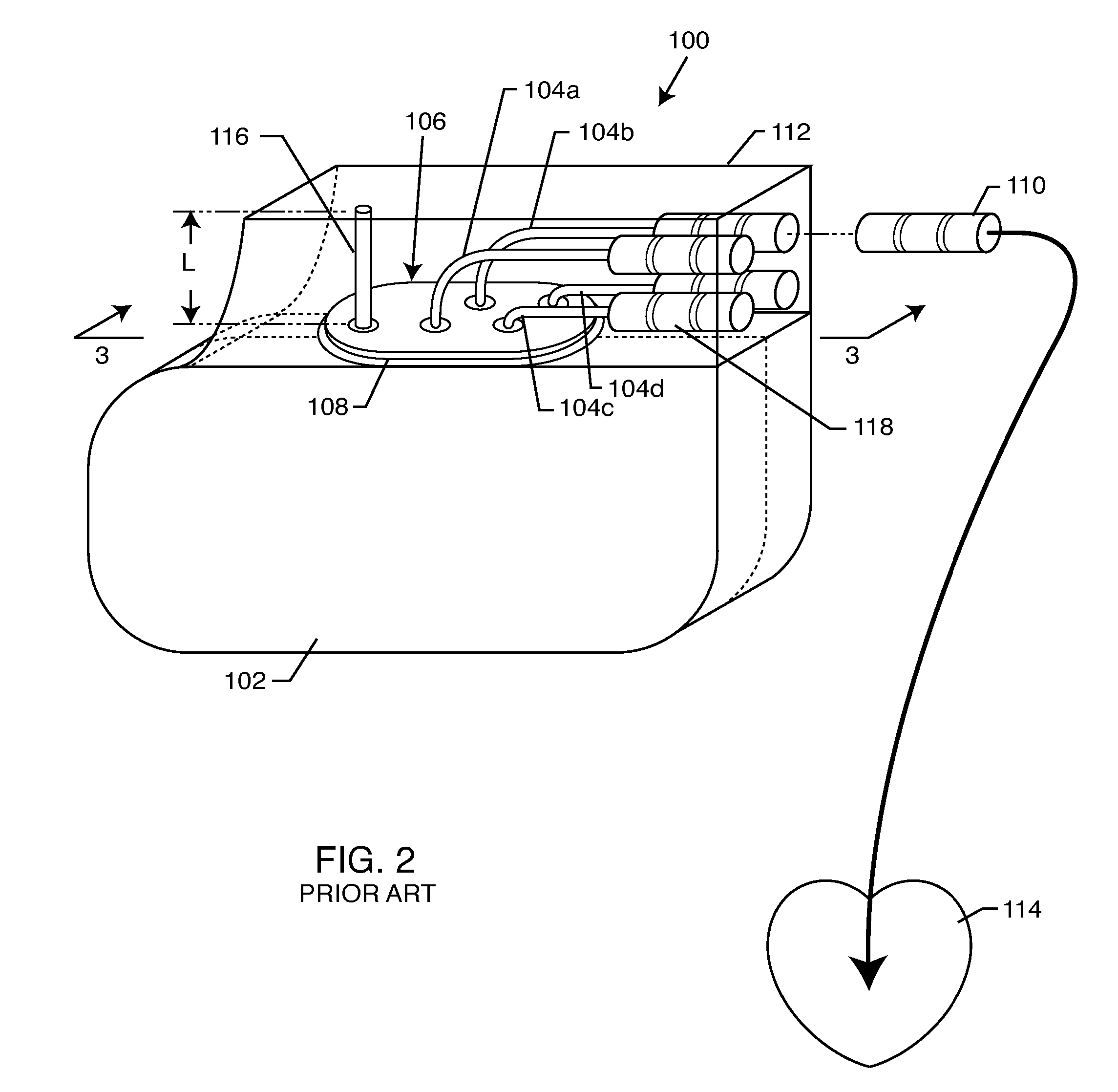
[0036]The present invention which resides in novel coaxial or rectilinear TANK filters is also designed to work in concert with the EMI filter which is typically used at the point of lead wire ingress and egress of the active implantable medical device. For example, see U.S. Pat. No. 6,999,818 filed Apr. 15, 2004, entitled INDUCTOR CAPACITOR EMI FILTER FOR HUMAN IMPLANT APPLICATIONS; U.S. patent application Ser. No. 11 / 097,999 filed Mar. 31, 2005, entitled APPARATUS AND PROCESS FOR REDUCING THE SUSCEPTIBILITY OF ACTIVE IMPLANTABLE MEDICAL DEVICES TO MEDICAL PROCEDURES SUCH AS MAGNETIC RESONANCE IMAGING; U.S. patent application Ser. No. 11 / 163,915 filed Nov. 3, 2005, entitled PROCESS FOR TUNING AN EMI FILTER TO REDUCE THE AMOUNT OF HEAT GENERATED IN IMPLANTED LEAD WIRES DURING MEDICAL PROCEDURES SUCH AS MAGNETIC RESONANCE IMAGING; and U.S. Patent Application No. 60 / 767,484 filed Apr. 3, 2006, entitled LOW LOSS BAND PASS FILTER FOR RF DISTANCE TELEMETRY PIN ANTENNAS OF ACTIVE IMPANTABLE MEDICAL DEVICES; the contents of all being incorporated herein by reference. All four of these documents describe novel inductor capacitor combinations for low pass EMI filter circuits. It is of particular interest that by increasing the number of circuit elements of the passive low pass filter at the AIMD hermetic feedthrough, one can reduce the overall capacitance value of said filter which primarily defines the input impedance of the AIMD. It is important to reduce the capacitance value to raise the input impedance of the AIMD. Increasing the input impedance of the AIMD will reduce the amount of current that would flow in lead wire systems at high frequencies such as those associated with the RF pulsed frequencies of MRI equipment. Accordingly, it is a feature of the present invention that the novel TANK filters are designed to be used in concert with prior art low pass filters.

Problems solved by technology

A major challenge for designing a TANK filter for human implant is that it must be very small in size, biocompatible, and highly reliable.

Method used


Image

  • Implantable lead with a band stop filter having a capacitor in parallel with an inductor embedded in a dielectric body
  • Implantable lead with a band stop filter having a capacitor in parallel with an inductor embedded in a dielectric body
  • Implantable lead with a band stop filter having a capacitor in parallel with an inductor embedded in a dielectric body

Examples


Embodiment Construction

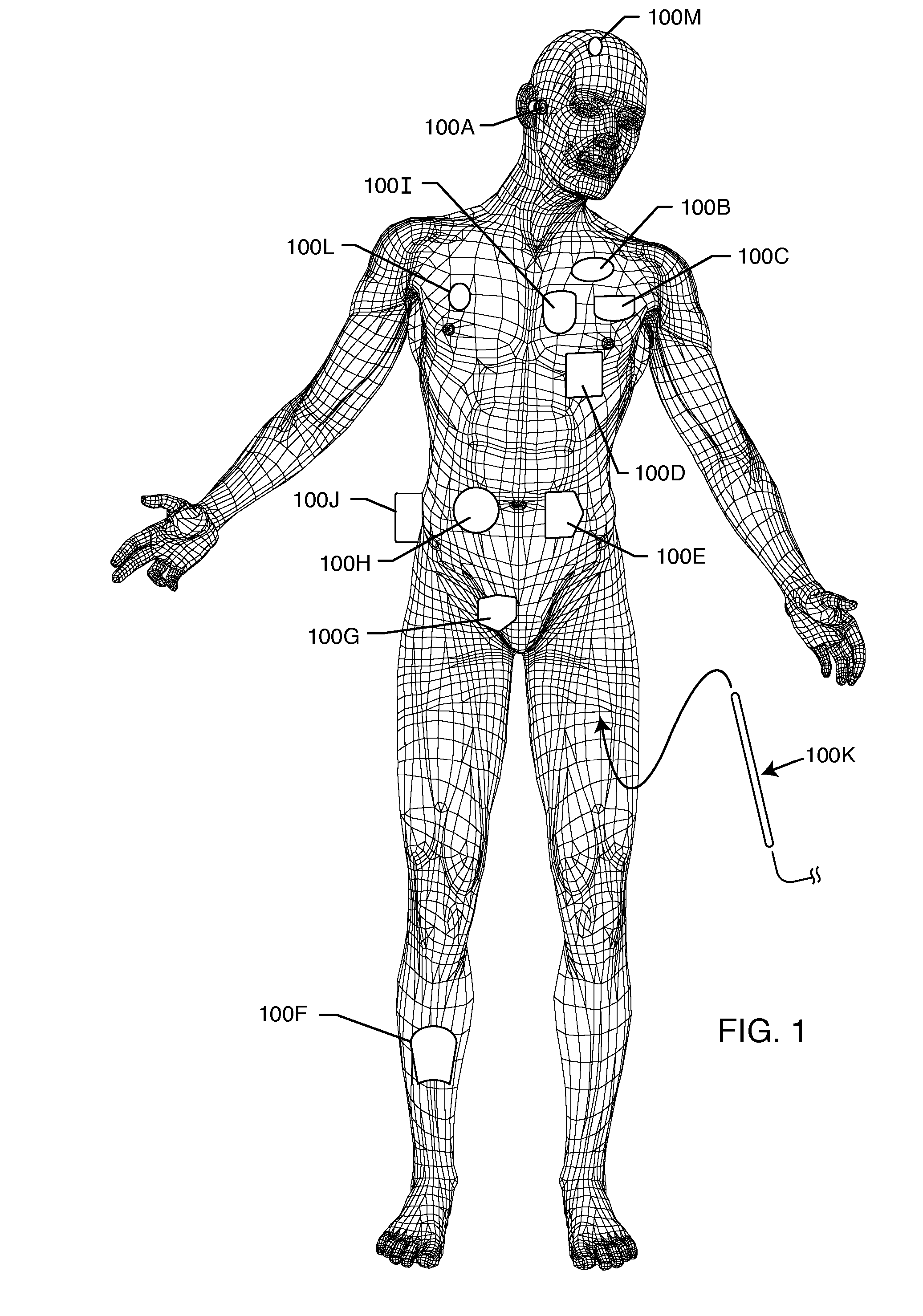
[0218]As shown in the drawings, for purposes of illustration, the present invention resides in the placement of TANK filters in series with lead wires or circuits of active medical devices to protect the patient and / or medical device from undesirable electromagnetic interference signals, such as those generated during MRI and other medical procedures. The present invention also resides in the design, manufacturing, and tuning of such TANK filters to be used in the lead wires or active medical devices. As will be explained more fully herein, the invention is applicable to a wide range of external medical devices, probes, catheters, monitoring lead wires and the like that may be temporarily inserted onto a patient or that a patient may be wearing or connected to during medical diagnostic procedures, such as MRI.

[0219]In the following description, functionally equivalent elements shown in various embodiments will often be referred to utilizing the same reference number.

[0220]FIG. 1 ill...


PUM


Abstract

A TANK filter is provided for a lead wire of an active medical device (AMD). The TANK filter includes a capacitor in parallel with an inductor. The parallel capacitor and inductor are placed in series with the lead wire of the AMD, wherein values of capacitance and inductance are selected such that the TANK filter is resonant at a selected frequency. In a preferred form, the TANK filter reduces or even eliminates the use of ferro-magnetic materials, and instead uses non-ferromagnetic materials so as to reduce or eliminate MRI image artifacts or the force or torque otherwise associated during an MRI image scan.

Description

CROSS-REFERENCE TO RELATED APPLICATIONS[0001]This application is a continuation-in-part of application Ser. No. 11 / 558,349, filed on Nov. 9, 2006, now U.S. Pat. No. 7,945,322, which is a continuation-in-part of application Ser. No. 11 / 423,073, filed on Jun. 8, 2006, now U.S. Pat. No. 8,244,370, which is a continuation-in-part of application Ser. No. 10 / 123,534, filed on Apr. 15, 2002, now U.S. Pat. No. 7,844,319, which is a continuation-in-part of application Ser. No. 09 / 428,990, filed on Nov. 29, 1999, now U.S. Pat. No. 6,701,176.[0002]application Ser. No. 11 / 558,349, filed on Nov. 9, 2006, now U.S. Pat. No. 7,945,322, claims priority from Pro. App. Ser. No. 60 / 597,125, filed on Nov. 11, 2005 and App. Ser. No. 10 / 123,534, filed on Apr. 15, 2002, now U.S. Pat. No. 7,844,319, claims priority from Pro. App. Ser. No. 60 / 283,725, filed on Apr. 13, 2001.BACKGROUND OF THE INVENTION[0003]This invention relates generally to electromagnetic interference (EMI) TANK filter assemblies, particul...

Claims


Application Information

Patent Timeline
Patent Type & Authority Patents(United States)
IPC IPC(8): A61N1/05H01G4/35H01G4/40H03H1/00A61N1/37A61N1/375H03H7/01A61N1/08
CPCA61N1/056H01G4/35H01G4/40H03H1/0007A61N1/3718A61N1/3754A61N2001/086H03H2001/0042H03H2001/005H03H7/1766A61N1/086
Inventor STEVENSON, ROBERT A.DABNEY, WARREN S.FRYSZ, CHRISTINE A.BRENDEL, RICHARD L.
Owner WILSON GREATBATCH LTD
Learn More