
Adaptive system for efficient transmission of power and data through acoustic media

a technology of adaptive system and acoustic medium, applied in the field of communication and power transmission, can solve problems such as and achieve the effect of reducing data and/or power transmission capabilities

Active Publication Date: 2015-06-09
RENESSELAER POLYTECHNIC INST
View PDF29 Cites 11 Cited by
  • Summary
  • Abstract
  • Description
  • Claims
  • Application Information

AI Technical Summary

Benefits of technology

[0012]It is an object of the present invention to provide an apparatus and method for the effective transmission of data and power through a barrier that may contain acoustic interfaces at boundaries of differing acoustic materials or conditions along the barrier, or which have acoustic properties that may vary with time or temperature or pressure, and that, in turn tend to degrade the data and / or power transmission. Differences in the densities and / or elastic moduli of the various materials comprising the channel can cause those elements to have differing acoustic properties, specifically their acoustic impedances may differ, resulting in a very frequency-selective transmission channels which can decrease its data and / or power transmission capabilities.
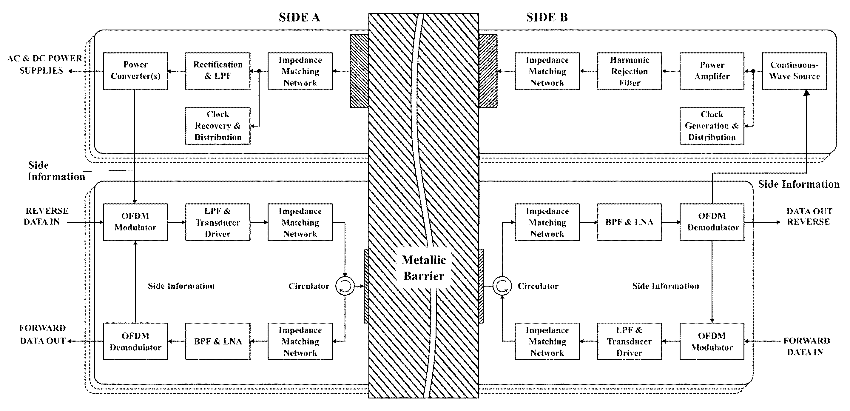
[0013]According to the present invention, high rate data and high power transmission are maintained by using Orthogonal Frequency-Division Multiplexing (OFDM) modulation with a cyclic prefix to send data at a high rate through the barrier channel and, because there are many parallel channels in the OFDM signal, by not using those channels that are at the harmonic frequencies of the power delivery signal. This maintains reliable data transmission without significant loss in the data rate.
[0015]The present invention thus uses bit loading. Bit loading is a technique for efficient data transmission, which involves selecting a modulation format for each sub-carrier in an OFDM signal according to its signal quality, e.g. the signal-to-noise ratio (SNR), of that particular sub-carrier. Power loading takes this process one step farther by also adjusting the power level of each individual channel in the OFDM signal. Power loading in addition to bit loading makes it possible to further increase the data rate of the communications link.
[0016]The present invention also provides a system for establishing data communication in both directions. If bit and / or power loading is used, it is necessary to send information, often called “side information,” from a receiver back to a transmitter that will instruct the transmitter how to adjust the modulation format (bit loading) and power (power loading) for each OFDM sub-carrier based on its received signal quality. In the following several methods for setting up this feedback channel are disclosed. When the communication of data is in the opposite direction of the power delivery, the power delivery signal itself can be modulated by the side information. This method avoids the need for a separate communications channel.
[0018]Accordingly, another object of the invention is to provide an apparatus and method for transmitting data and power through a barrier using ultrasonic waves. Ultrasonic channels are formed through the barrier by coupling ultrasonic transducers to opposite sides of the barrier. A power transmitter sends power by a continuous-wave (CW) signal over a channel and forward and reverse data transmitters send forward and reverse data signals by orthogonal frequency division multiplexing (OFDM) over a channel. The data signals are made up of plural sub-carriers at plural different sub-carrier frequencies with none of the sub-carriers of the forward transmission signal being at a power harmonic frequency for the power transmission to avoid interference and maximize power transmission.

Problems solved by technology

Differences in the densities and / or elastic moduli of the various materials comprising the channel can cause those elements to have differing acoustic properties, specifically their acoustic impedances may differ, resulting in a very frequency-selective transmission channels which can decrease its data and / or power transmission capabilities.

Method used


Image

  • Adaptive system for efficient transmission of power and data through acoustic media
  • Adaptive system for efficient transmission of power and data through acoustic media
  • Adaptive system for efficient transmission of power and data through acoustic media

Examples


Embodiment Construction

[0041]Referring now to the drawings, in which like reference numerals are used to refer to the same or similar elements, FIG. 1 shows an example of an acoustic-electric channel through a barrier 10 for transmitting signals through solid or other media, with an electroacoustic transducer 12 and 14 on each side of the barrier 10. Throughout this disclosure, the transducers 12 and 14 shown in the drawings symbolize the transducers proper plus their connection to the barrier wall, i.e. electrodes with or without epoxy, acoustical couplant, electrical insulation layer, acoustical transition layers, etc. Such an arrangement can be especially advantageous when the media is electrically conducting, appreciably thick and when maintaining its structural integrity is critical, e.g. by not drilling holes through the barrier. This is because Faraday shielding effects prevent conventional electromagnetic wireless signals from passing through conducting barriers and penetrating certain barriers wo...


PUM


Abstract

An apparatus and method for transmitting data and power through a metal barrier using ultrasonic waves, having ultrasonic transmission channels through the barrier formed by coupling ultrasonic transducers on opposite sides of the barrier. A power transmitter sends power over a channel and forward and reverse data transmitters send forward and reverse data signals by orthogonal frequency-division multiplexing OFDM over a separate channel. The data signals are made up of plural sub-carriers at plural different sub-carrier frequencies with none of the sub-carriers of the forward transmission signal being at a power harmonic frequency.

Description

CROSS-REFERENCE TO RELATED APPLICATION[0001]This application claims priority on U.S. Provisional Patent Application No. 61 / 517,037 filed Apr. 12, 2011 which is incorporated herein by reference.FIELD AND BACKGROUND OF THE INVENTION[0002]The present invention relates generally to the field of communication and power transmission, and in particular to wireless communication and power transmission through a barrier using ultrasonic waves.[0003]Published patent application US2010 / 0027379, published Feb. 4, 2010 and incorporated herein by reference, discloses an ULTRASONIC THROUGH-WALL COMMUNICATION (UTWC) SYSTEM for communicating digital information through a barrier in the form of a thick metal wall, using ultrasonic techniques so that no through-holes are needed in the barrier. Using this system, signals can be transmitted through the barrier. For example, sensor signals that monitor conditions on one side of the barrier, can be transmitted to the other side of the barrier. The barrier...

Claims


Application Information

Patent Timeline
Patent Type & Authority Patents(United States)
IPC IPC(8): H04J11/00H04B11/00H04L5/00H04L27/26
CPCH04J11/00H04L27/2698H04B11/00H04L5/0046H04L27/2697H04L27/2657
Inventor LAWRY, TRISTAN J.SAULNIER, GARY J.WILT, KYLE R.ASHDOWN, JONATHAN D.SCARTON, HENRY A.
Owner RENESSELAER POLYTECHNIC INST
Learn More