Control apparatus for vehicular power transmitting apparatus

a control apparatus and transmission device technology, applied in the direction of clutches, gearing elements, gearing, etc., can solve the problems of inability to restart slip control, heat resistance may become even more of an issue, and the friction element durability may decrease depending on the situation, so as to achieve the effect of limiting the range, obtaining more easily, and unlimited the rang

Inactive Publication Date: 2015-06-09
TOYOTA JIDOSHA KK
View PDF18 Cites 2 Cited by
  • Summary
  • Abstract
  • Description
  • Claims
  • Application Information

AI Technical Summary

Benefits of technology

[0009]In view of the situation described above, the invention provides a control apparatus for a vehicular power transmitting apparatus that is capable of increasing, as much as possible, the number of opportunities to execute slip control while suppressing a decrease in durability of a friction clutch.
[0011]As described above, a predetermined relationship is provided that has an unlimited range where slip control a next time is repeatedly executed indefinitely, a limited range where slip control the next time is repeatedly executed only a predetermined number of times, and a prohibited range where slip control the next time is prohibited, and that has a generated heat amount in the friction clutch during the slip control and an elapsed time after the slip control ends as variables. Therefore, by executing take-off slip control according to this predetermined relationship, the region in which take-off slip control the next time had been prohibited because take-off slip control the next time is unable to be executed repeatedly indefinitely, but is able to be repeatedly executed only a predetermined number of times, is made the limited region, such that take-off slip control the next time is allowed to be repeatedly, executed only a predetermined number of times. As a result, the number of opportunities to execute take-off slip control can be increased as much as possible while suppressing a decrease in the durability of the friction clutch. Here, a map or an expression in which the unlimited range, the limited range, and the prohibited range are indicated, with the generated heat amount in the friction clutch during the slip control and the elapsed time after the slip control ends as variables may be provided.
[0012]Also, in the control apparatus described above, the slip control may be executed with the generated heat amount in one time of control having a predetermined maximum generated heat amount that is set in advance as an upper limit, and allowing the slip control the next time may be allowing slip control until the predetermined maximum generated heat amount for one time of control is reached. Accordingly, a decrease in the durability of the friction clutch due to the slip control that has been allowed to be repeatedly executed actually being executed is able to be reliably suppressed.
[0014]Also, in the control apparatus described above, the predetermined relationship may be set such that as the generated heat amount during the slip control decreases, the limited range is obtained more easily than the prohibited range and the unlimited range is obtained more easily than the limited range, and as the elapsed time after the slip control ends becomes longer, the limited range is obtained more easily than the prohibited range and the unlimited range is obtained more easily than the limited range. Accordingly, slip control is able to be even more appropriately executed according to the predetermined relationship.
[0015]Also, in the control apparatus described above, the friction clutch may be a lock-up clutch capable of directly connecting together input / output rotating members of a fluid power transmitting device that transmits power of the engine to the driving wheel side, and the slip control may be lock-up slip control that slip-engages the lock-up clutch when a vehicle is running. Accordingly, the number of opportunities to execute lock-up slip control can be increased as much as possible while suppressing a decrease in the durability of the lock-up clutch. Thus, fuel efficiency can be improved.
[0016]Also, in the control apparatus described above, the lock-up slip control may be take-off lock-up slip control that slip-engages the lock-up clutch such that a speed of the engine comes to match a target value when the vehicle takes off. Therefore, the number of opportunities to execute take-off slip control can be increased as much as possible while suppressing a decrease in the durability of the lock-up clutch, to combat the fact that repeated execution of take-off slip control may not be easily allowed due to the generated heat amount becoming relatively large when take-off slip control is executed.

Problems solved by technology

Therefore, the durability of the friction elements may decrease depending on the manner in which slip control is executed.
Therefore, the thermal load of the lock-up clutch is large, so heat resistance may become even more of an issue.
When the required restart time is set as described above, slip control may be unable to be restarted even in a state in which slip control would normally be able to be restarted.

Method used


Image

  • Control apparatus for vehicular power transmitting apparatus
  • Control apparatus for vehicular power transmitting apparatus
  • Control apparatus for vehicular power transmitting apparatus

Examples


Embodiment Construction

[0026]In the invention, a diesel engine or a gasoline engine or the like, such as an internal combustion engine that generates power by burning fuel, for example, is preferably used as the engine, but another prime mover such as an electric motor may also be used in combination with an engine.

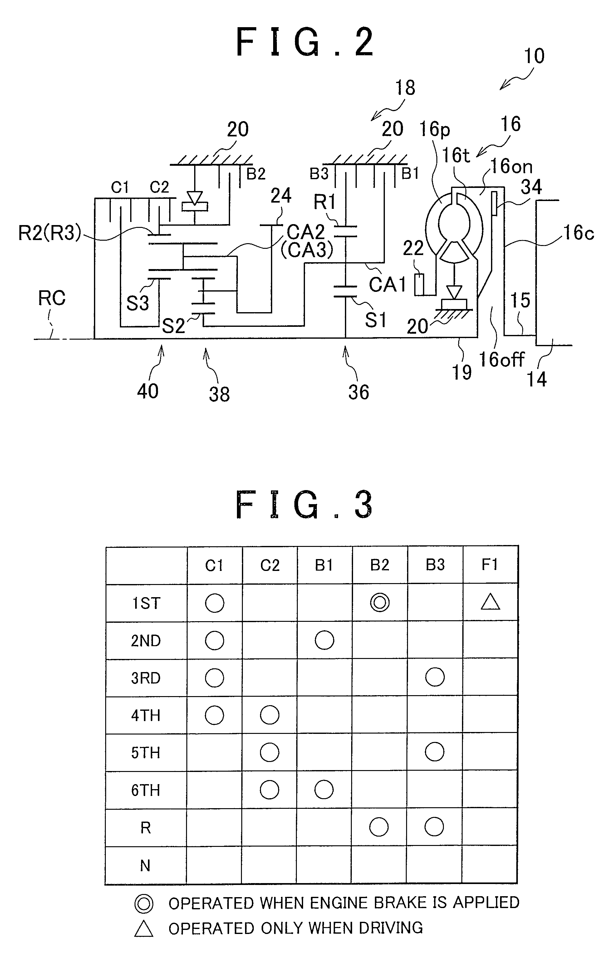
[0027]Also, the vehicular power transmitting apparatus may include a transmission in a power transmitting path between the engine and the driving wheels. This transmission may be formed by, for example, i) any one of various planetary gear automatic transmissions that have, for example, four, five, six, or more forward speeds, in which a plurality of gear speeds (i.e., speeds) are alternatively established by selectively connecting rotating elements of a, plurality of planetary gear sets together by an engagement apparatus, ii) a synchronous mesh twin shaft parallel axis-type automatic transmission that is a synchronous mesh twin shaft parallel axis-type transmission provided with a plurality o...


PUM


Abstract

A map is provided that has an unlimited region where a take-off slip-engagement the next time is repeatedly executed indefinitely, a limited region where the take-off slip-engagement the next time is repeatedly executed only once, and a prohibited region where the take-off slip-engagement the next time is prohibited, and has a generated heat amount during the take-off slip-engagement and an elapsed time after the lock-up slip-engagement ends as variables. Therefore, a region in which the take-off slip-engagement the next time had been prohibited because the take-off slip-engagement the next time is unable to be repeatedly executed indefinitely even though it is able to be repeatedly executed only once is made the limited region, so the take-off slip-engagement the next time is allowed to be repeatedly executed only once.

Description

INCORPORATION BY REFERENCE[0001]The disclosure of Japanese Patent Application No. 2011-014199 filed on Jan. 26, 2011, including the specification, drawings and abstract is incorporated herein by references in its entirety.BACKGROUND OF THE INVENTION[0002]1. Field of the Invention[0003]The invention relates to a control apparatus for a vehicular power transmitting apparatus that performs slip control of a friction clutch.[0004]2. Description of the Related Art[0005]A friction clutch that is provided in a power transmitting path between an engine and driving wheels is well known. Examples include friction clutches such as a forward clutch (i.e., a starting clutch or take-off clutch) and lock-up clutch described in Japanese Patent Application Publication No. 2006-226333 (JP-A-2006-226333), Japanese Patent Application Publication No. 2005-351357 (JP-A-2005-351357), and Japanese Patent Application Publication No. 2006-300206 (JP-A-2006-300206). Generally, this kind of a friction clutch h...

Claims


Application Information

Patent Timeline
Patent Type & Authority Patents(United States)
IPC IPC(8): B60W10/02B60W10/06F16H61/14F16D48/08F16H59/72F16H47/06
CPCB60W10/02F16D48/08F16H61/143B60W10/06Y10T477/755Y10T477/63385Y10T477/653F16H47/06F16D2500/30405F16D2500/30406F16D2500/3166F16D2500/50224F16D2500/5106F16D2500/70426F16H2059/725F16H2061/145F16H2312/02
Inventor DODO, KOHEINAKASHIMA, YOICHIMUTO, ATSUSHIFUJIKANE, TSUYOSHIMATSUBARA, KEIGOINOUE, JUNICHI
Owner TOYOTA JIDOSHA KK
Why Eureka
Try Eureka