
Tool for clamping using sides of workpieces

a tool and workpiece technology, applied in the field of tools for clamping using the sides of workpieces, can solve problems affecting the and achieve the effects of convenient clamping, reliable clamping and fixing, and guaranteed processing quality of box workpieces

Inactive Publication Date: 2015-06-09
ZHEJIANG LINIX MOTOR
View PDF9 Cites 2 Cited by
  • Summary
  • Abstract
  • Description
  • Claims
  • Application Information

AI Technical Summary

Benefits of technology

[0003]The invention provides a tool for clamping using sides of workpieces, which is convenient in clamping, and is capable of reliably clamping and fixing box workpieces using the sides of the workpieces and guaranteeing the processing quality of box workpieces. The tool for clamping using sides of workpieces solves the problem that the existing clamping tools cannot tightly press the box workpieces, which leads to a possibility of movement of the box workpieces in location during processing to affect the processing quality of the box workpieces.
[0005]Preferably, the width of the rectangle groove on the bottom of the V-shaped groove is almost equal to that of the opening of the vertical V-shaped groove, therefore, the thickness of the root portions of the two side walls of each elastic seat maybe decreased, to make the two side walls of the elastic seat more likely to be deformed, so as to reduce the resistance against down pressing for the V-shaped pressing block.
[0007]Preferably, an arc-shaped pit is arranged on the bottom of the horizontal V-shaped groove of the V-shaped locating block to enhance the elasticity of the horizontal V-shaped groove of the V-shaped locating block, so that tighter contact between the horizontal V-shaped groove and the box workpiece may be accomplished.
[0009]Hence, the invention has the advantages that clamping is convenient, box workpieces can be reliably clamped and fixed using the sides of the workpieces, the processing quality of box workpieces can be guaranteed, and the clamping efficiency can be improved.

Problems solved by technology

The tool for clamping using sides of workpieces solves the problem that the existing clamping tools cannot tightly press the box workpieces, which leads to a possibility of movement of the box workpieces in location during processing to affect the processing quality of the box workpieces.

Method used


Image

  • Tool for clamping using sides of workpieces
  • Tool for clamping using sides of workpieces
  • Tool for clamping using sides of workpieces

Examples


embodiment

[0017

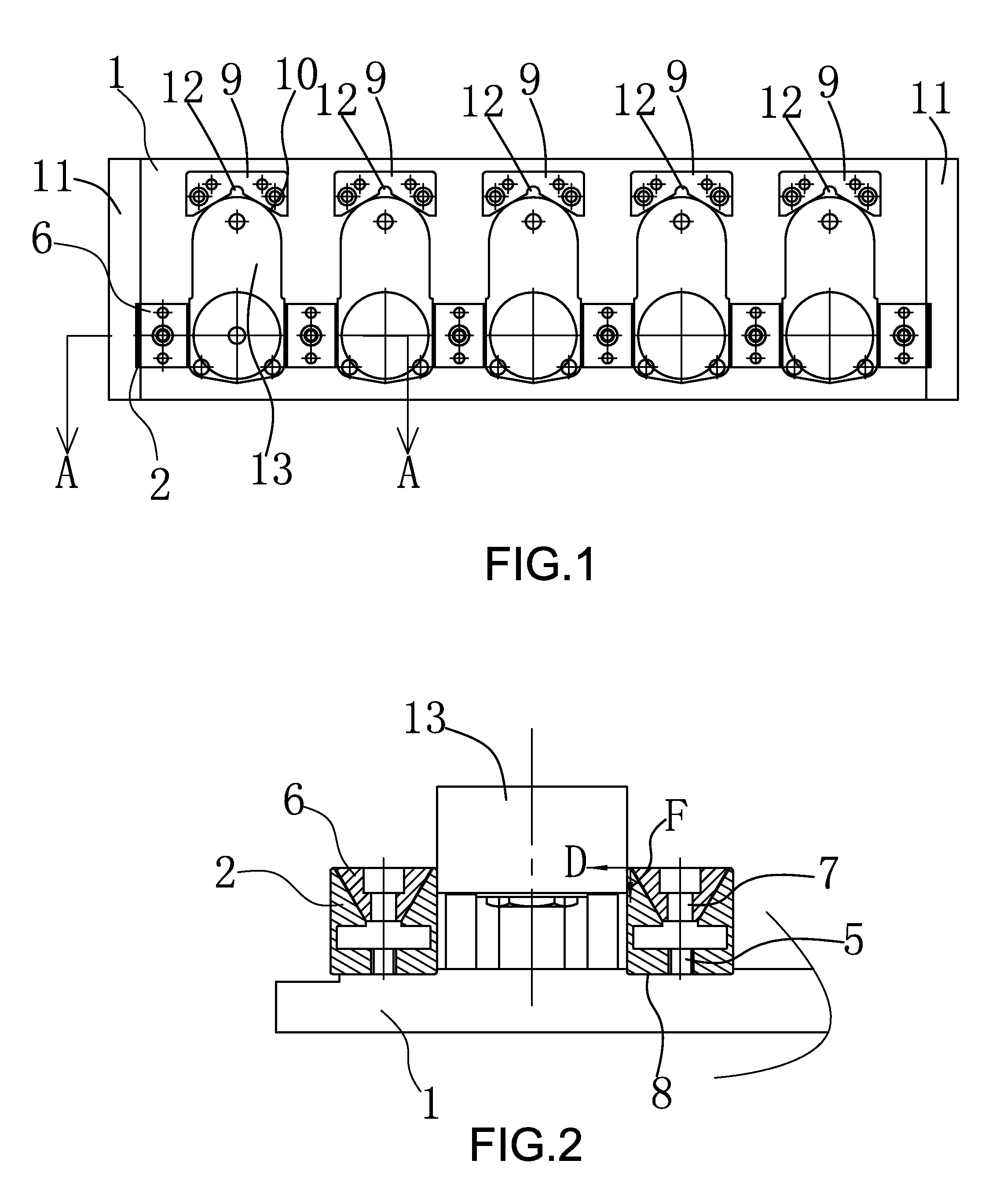
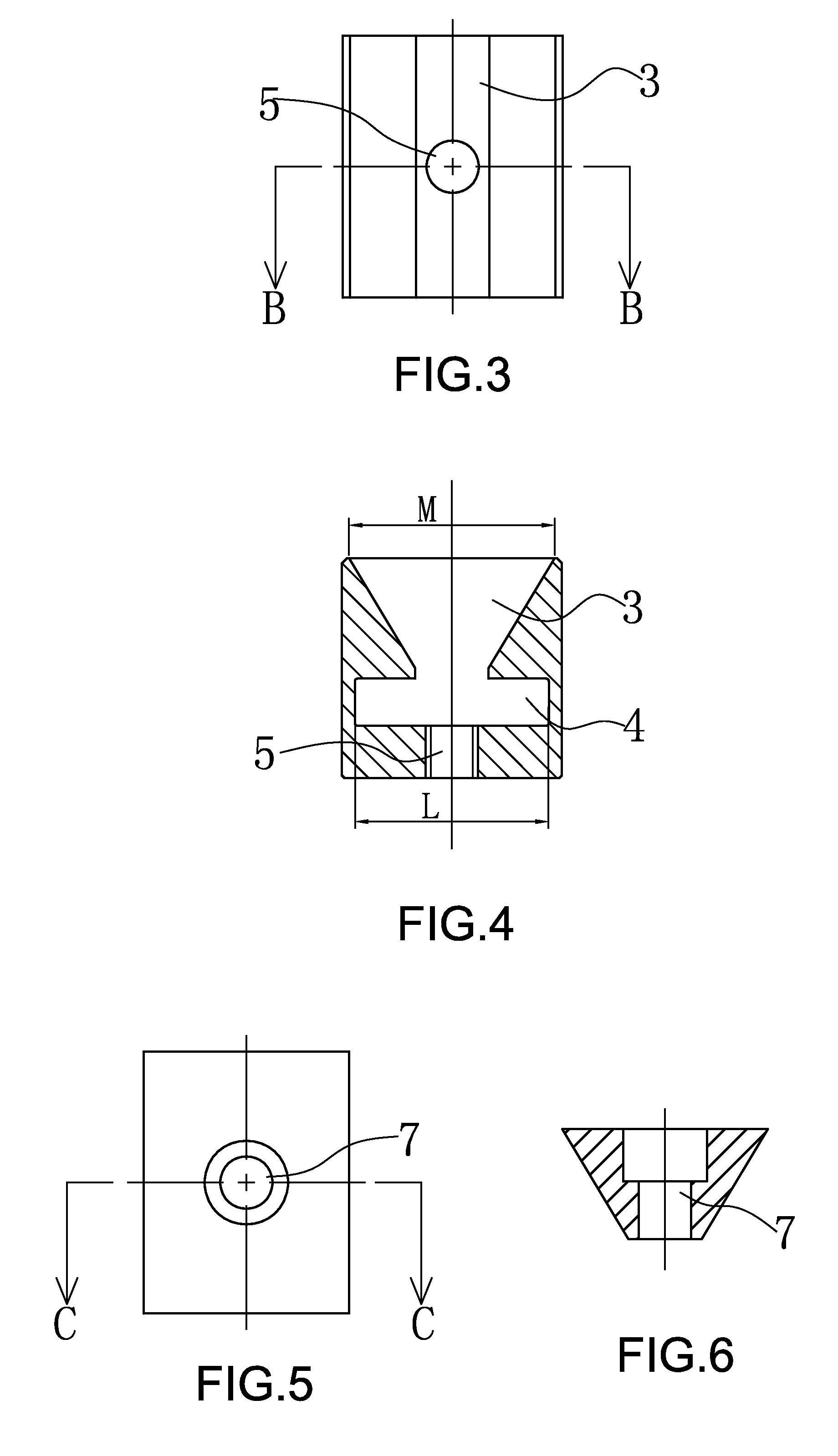
[0018]As shown in FIG. 1 and FIG. 2, the tool for clamping using sides of workpieces comprises a soleplate 1, two ends of the soleplate 1 are provided with step faces 11, respectively, one side of the soleplate 1 is fixed with six elastic seats 2 arranged at interval, shallow slots 8 are arranged at positions of the soleplate where the soleplate is fitted with the elastic seats 2, and the shallow slots 8 fit with the lower end faces of the elastic seats 2. As shown in FIG. 3 and FIG. 4, each elastic seat 2 is provided with a vertical V-shaped groove 3, the bottom of the vertical V-shaped groove 3 is provided with a rectangle groove 4, the bottom of the rectangle groove 4 is provided with a threaded hole 5, the width L of the rectangle groove 4 on the bottom of the vertical V-shaped groove is almost equal to the width M of the opening of the vertical V-shaped groove 3.

[0019]As shown in FIG. 1 and FIG. 2, a V-shaped pressing block 6 is fitted in the vertical V-shaped groove 3. As...


PUM


Abstract

The invention relates to a tool for clamping using sides of workpieces, in particular to a tool for clamping and processing workpieces like boxes using sides of the box workpieces, belonging to the technical field of tools for clamping used in the processing center to process workpieces. The tool for clamping using sides of workpieces comprises a soleplate, wherein one side of the soleplate is fixed with multiple elastic seats arranged at interval, the elastic seats are provided with vertical V-shaped grooves, the bottom of each vertical V-shaped groove is provided with a rectangle groove, the bottom of the rectangle groove is provided with a threaded hole, a V-shaped pressing block is fitted in the vertical V-shaped groove, a through hole which is coaxial with the threaded hole on the bottom of the rectangle groove is formed on the V-shaped pressing block, and a bolt passes through the through hole on the V-shaped pressing block to fit with the threaded hole on the bottom of the rectangle groove; and, the other side of the soleplate opposite to the elastic seats is provided with multiple V-shaped locating blocks arranged at interval, the gap between each two adjacent elastic seats corresponds to one V-shaped locating block, and each V-shaped locating block is provided with a horizontal V-shaped groove, the opening of which faces the gap between two adjacent elastic seats.

Description

TECHNICAL FIELD OF THE INVENTION[0001]The invention relates to a tool for clamping using sides of workpieces, in particular to a tool for clamping and processing workpieces like boxes using sides of the box workpieces, belonging to the technical field of tools for clamping used in the processing center to process workpieces.BACKGROUND OF THE INVENTION[0002]When boring or facing box workpieces, such as the box body of a reduction box, the end faces of the box workpieces are required to be set apart, therefore, the box workpieces can be clamped using only the sides of the box workpieces. However, the existing tools for clamping act on the sides of workpieces through pressing blocks, the pressing blocks are often difficult to tightly contact with the sides of the box workpieces as the sides of the box workpieces usually have a draft caused by that the box workpieces are generally processed in a die-casting way. As a result, the box workpieces cannot be tightly pressed, which leads to a...

Claims


Application Information

Patent Timeline
Patent Type & Authority Patents(United States)
IPC IPC(8): B23Q3/02B23Q3/10B23Q3/06B25B5/08
CPCB23Q3/06B23Q3/061B25B5/08B23Q3/104B23B29/24B25B5/10
Inventor ZHU, YANZHAO
Owner ZHEJIANG LINIX MOTOR
Learn More